
Patents for May
Patents from the USPTO as compiled by the editors of WCTI for May 2025.
Cable Reel
US Patent 12269706
Published April 8, 2025
Inventors: Rakesh Thakare, Cary, NC, USA; Caichun Song, Changzhou, China; Phillip S. Bowen, Chatham, VA, USA; Marvin Bryant, Chatham, VA, USA; Paul R. Boucher, Callands, VA, USA; and Barry Holt, Ottawa, ON, Canada
Assignee: Times Fiber Communications, Inc., Wallingford, CT, USA
A cable reel that includes a one-piece frame body, a flange separate from the frame body and a hub member therebetween. The one-piece frame body includes an outer frame portion and an inner flange portion. The flange has an inner side that faces the inner side of the one-piece frame body. The hub member is located between the one-piece frame body and the flange along a central longitudinal axis of the cable reel. The hub member has a first end that rotatably couples to the inner flange portion of the one-piece frame body and a second end that couples to the flange. The hub member is configured to support a coil of cable and is sized to be received inside of an inner diameter of the coil of cable. The flange and the hub member rotate together with respect to the one-piece frame body.
Stainless Steel Flux Cored Wire for Manufacturing LNG Tank
US Patent 12269128
Published April 8, 2025
Inventors: Hee Dae Im, Gyeongsangnam-do, South Korea; Chang Hyun Choi, Gyeongsangnam-do, South Korea; Woong Kil, Gyeongsangnam-do, South Korea
Assignee: ESAB SeAHP Corp., Gyeongsangnam-do, South Korea
Provided is a stainless steel flux-cored wire for manufacturing an LNG tank. From the stainless steel flux-cored wire, it is possible to obtain a weld metal having excellent tensile strength and impact value by adjusting the contents of Mn, Mo, and Cr. The stainless steel flux-cored wire is applicable to welding of 9% nickel steel, high manganese steel and stainless steel materials and can provide a weld metal having excellent cryogenic toughness in a weld zone because the contents of Mn, Mo, and Cr are adjusted.
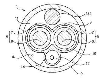
Heavy-Current Charging Cable for Charging an Electric Vehicle
US Patent 12263745
Published April 1, 2025
Inventors: Matteo Bortolato, Trebaseleghe, Italy; Emmanuel Logakis, Baden-Dättwil, Swtizerland; Moritz Boehm, Mellingen, Switzerland; and Jean-Marc Oppliger, Fislisbach, Switzerland
Assignee: ABB E-mobility B.V., Delft, Netherlands
A charging cable includes a ground conductor and extending in a longitudinal direction, at least two heavy-current power wires for conducting positive and negative direct current, each comprising a power conductor and insulation, the heavy-current power wires extending parallel to the ground wire, a liquid tight inner sheath extending in the longitudinal direction and surrounding the heavy-current power wires to define a first hollow area between and around the heavy-current power wires, liquid coolant being provided between the heavy-current power wires along the longitudinal direction, wherein the liquid tight inner sheath comprises a second hollow area extending in the longitudinal direction, arranged adjacent to at least one of the heavy-current power wires and comprising liquid coolant to flow within the second hollow area, and a liquid tight outer sheath extending in the longitudinal direction and surrounding the inner sheath and the ground heavy-current wire.
Steel Wire Rod Having Excellent Spheroidizing Heat Treatment Properties and Method of Manufacturing Same
US Patent 12264379
Published April 1, 2025
Inventors: Sang-Yoon Lee, Gyeongsangbuk-do, South Korea; In-Gyu Park, Gyeongsangbuk-do, South Korea; Jae-Seung Lee, Gyeongsangbuk-do, South Korea; and Byoung-Gab Lee, Gyeongsangbuk-do, South Korea
Assignee: POSCO, Pohang-si, South Korea
An embodiment of the present invention provides a wire rod and a method of manufacturing same. The wire rod comprises, by weight %, 0.3-0.5 wt % of C, 0.02-0.4 wt % of Si, 1.0-1.5 wt % of Mn, 0.3-0.7 wt % of Cr, 0.003 wt % or less (exclusive of 0 wt %) of B, less than 0.03 wt % (exclusive of 0 wt %) of Ti, 0.03 wt % or less (inclusive of 0 wt %) of P, 0.01 wt % or less (inclusive of 0 wt %) of S, 0.02-0.05 wt % of Al, 0.001-0.01 wt % of N, and the balance being Fe and inevitable impurities, wherein a microstructure is a complex structure having a main phase of ferrite+pearlite, with at least one of bainite or martensite accounting for 5 area % or less (inclusive of 0%), and has a cementite average aspect ratio of 35 or less in an area covering ⅖-⅗ of the diameter.
Rotatable Cable Reel
US Patent 12264036
Published April 1, 2025
Inventors: Andrew Cody Norton, Carrollton, GA, USA; Roy Savoy Bearden, Temple, GA, USA; Juan Alberto Galindo Gonzalez, Powder Springs, GA, USA; and Franklin Clarence Calhoun, Carrollton, GA, USA
Assignee: Southwire Company, LLC, Carrollton, GA, USA
A cable reel of the present disclosure can include two flanges and a central drum being independently rotatable from one another. The drum, which can be configured to receive a cable, can be mounted on an axle. The two flanges can be rotationally mounted on the axle at opposing distal ends of the axle. Bearings in the flanges can allow for a full rotation of the flanges about the axle. The cable reel can also include a locking pin for locking rotation of a flange with rotation of the drum.
Electrical Wire Having Leakage Current Limiting Function
US Patent 12266455
Published April 1, 2025
Inventor: Ho Seok Lee, Busan, South Korea
Assignee: Vision Tech Corporation, Busan, South Korea
The present disclosure relates to an electrical wire having a leakage current limiting function, in which, since a neutral line is provided to have a greater cross-sectional area than that of a phase voltage line, a leakage current leaking from the phase voltage line may be limited, and thus the risk of electric shock to the human body due to the leakage current may be minimized.
Single-Layer Multi-Strand Cable Having Improved Energy at Break and an Improved Total Elongation
US Patent 12258707
Published March 25, 2025
Inventors: Gael Pataut, Clermont-Ferrand, France; Henri Barguet, Clermont-Ferrand, France; Lucas Lauby, Clermont-Ferrand, France; and Olivier Reix, Clermont-Ferrand, France
Assignee: Michelin, Clermont-Ferrand, France
A multi-strand cord (50) having a 1×N structure comprises a single layer (52) of N strands (54) wound in a helix about a main axis (A), each strand (54) having one layer (56) of metal filaments (F1) and comprising M>1 metal filaments wound in a helix about an axis (B). The cord (50) has a total elongation At>8.10% and the energy-at-break indicator Er of the cord (50), defined by Er=∫0Atσ(Ai)×dAi where σ(Ai) is the tensile stress in MPa measured at the elongation Ai and dAi is the elongation such that Er is strictly greater than 52 MJ/m3.
Communication Cable
US Patent 12260970
Published March 25, 2025
Inventors: Yuta Yasuyoshi, Mie, Japan; and Tatsuya Shimada, Mie, Japan
Assignees: Autonetworks Technologies, Ltd., Mie, Japan; Sumitomo Wiring Systems, Ltd., Mie, Japan; and Sumitomo Electric Industries, Ltd., Osaka, Japan
A communication cable 1 is provided with a conductor 2, an insulation layer 3 containing an organic polymer and covering an outer periphery of the conductor 2, a metal foil 5 for covering an outer periphery of the insulation layer 3 and a magnetic sheath layer 7 containing an organic polymer and a powdered magnetic material and covering an outer periphery of the metal foil 5. A tensile modulus of elasticity of the magnetic sheath layer 7 is lower than that of the insulation layer 3. Assuming that an organic polymer having a melting point of 100°C. or lower is a low melting point polymer and a mass ratio of the low melting point polymer to organic polymer components constituting each layer is a low melting point component ratio, the low melting point component ratio is larger in the magnetic sheath layer 7 than in the insulation layer 3.
Stranded Wire Conductors and Methods for Manufacturing Stranded Wires
US Patent 12260974
Published March 25, 2025
Inventor: Xuebin Li, Huzhou, China
Assignee: Huzhou Jin Tai Conductor Technlology Co., Ltd., Huzhou, China
A stranded wire conductor and a method for manufacturing a stranded wire, wherein the stranded wire conductor is made of a plurality of composite wire monofilaments stranded together, each having a nickel-tantalum-tungsten core wire, a conductive alloy tube wrapped around an outside of the nickel-tantalum-tungsten core wire, and a plating disposed on an outside of the conductive alloy tube. By stranding the plurality of composite wire monofilaments together to form the stranded wire conductor, and the composite wire monofilament is made of the nickel-tantalum-tungsten core wire, the conductive alloy tube and the plating, the stranded wire conductor can still maintain a high strength and conductivity when operating at a temperature in a range of 600°C to 700°C.
Compound Superconducting Twisted Wire and Rewinding Method For Compound Superconducting Twisted Wire
US Patent 12255000
Published March 18, 2025
Inventors: Masahiro Sugimoto, Tokyo, Japan; Hirokazu Tsubouchi, Tokyo, Japan; Daisuke Asami, Tokyo, Japan; and Hideki Ii, Tokyo, Japan; Satoshi Awaji, Sendai, Japan; and Hidetoshi Oguro, Hiratsuka, Japan
Assignees: Furukawa Electric Co., Ltd., Tokyo, Japan; Tohoku University, Sendai, Japan; and Tokai University Educational System, Tokyo, Japan
A compound superconducting twisted wire includes compound superconducting strands being twisted to form a twisted structure, in which each of the compound superconducting strands includes a compound superconductor part, a reinforcing part and a stabilizing part. The compound superconductor part includes compound superconducting filaments and a first matrix, the compound superconducting filaments each including a compound superconducting phase. The reinforcing part is disposed on an outer circumferential side of the compound superconductor part and includes reinforcing filaments and a second matrix. The stabilizing part is disposed on at least one side of an inner circumferential side and an outer circumferential side of the reinforcing part. A volume ratio of the reinforcing part relative to the compound superconducting strand is larger than a volume ratio of the compound superconductor part relative to the compound superconducting strand.
Electric Vehicle Charging Cable
US Patent 12252024
Published March 18, 2025
Inventors: Hyun Woong Kim, Suwon-si, South Korea; Jae Bok Lee, Seoul, South Korea; Dong Kyun Yoo, Yongin-si, South Korea; and Uk Yeol Choi, Seoul, South Korea
Assignees: LS Cable & System Ltd., Anyang-si, South Korea; and LS EV Korea Ltd., Gunpo-si, South Korea
The present disclosure relates to an electric vehicle charging cable, in which a cooling fluid is used to efficiently cool heat generated during charging of an electric vehicle, a thermally conductive material is added as well as the cooling fluid to improve cooling performance, thereby preventing damage to inner components due to heat, safety accidents such as fire are prevented, and a diameter of the cable is minimized.
High Density Thermistor Cable
US Patent 12253424
Published March 18, 2025
Inventor: Michael Melnychuk, Nisku, AB, Canada
Assignee: Precise Downhole Services Ltd., Nisku, AB, Canada
A thermistor cable is formed from a tubing and a plurality of thermistor conductors bundled within the tubing, wherein each thermistor conductor forms a junction with a shared thermistor conductor to form a thermistor junction, and each thermistor junction is attached to a support cable in a thermistor bundle. The cable is formed by pulling the thermistor bundle into the tubing.
High Strength Data Transmission Cable
US Patent 12248194
Published March 11, 2025
Inventor: Hjortur Erlendsson, Kopavogur, Iceland
Assignee: Hampidjan HF, Reykjavik, Iceland
Disclosed is a non-steel high strength data transmission cable having a strength member (5) and a core (1). The high strength data transmission cable includes a length of a core-cable (10), the length of core-cable (10) includes core (1) plus at least one fiber-optic conductor (2) that is: (i) disposed in a helical shape; and (ii) completely encased in a solid, flexible material. Also disclosed is a process for making a high strength data transmission cable. The high strength data transmission cable is capable of being wound on a winch under tensions and surging shocks experienced by a fishing trawler, and provides high quality data signal transmission and resolution so as to permit use for transmitting data during fish trawl operation from high-resolution sonars used to monitor fish caught.
Wire Straightening Device, Wire Processing Device Having the Same, and Wire Straightening Method
US Patent 12246373
Published March 11, 2025
Inventor: Takashi Oshima, Takarazuka, Japan
Assignee: Shinmaywa Industries, Ltd., Hyogo, Japan
An object is to provide a wire straightening device and a wire straightening method, with which it is possible to automatically set the roller spacing in accordance with the type of the wire and to further adjust the roller spacing during operation. A wire straightening device (20) includes a preset value obtaining device that obtains a preset value of roller spacing, which is predetermined for each type of wire (2); a roller spacing automatic setting device that drives an actuator (26a) so that the roller spacing becomes equal to the preset value when the type of the wire (2) is input; and a roller spacing changing device that changes the roller spacing based on an operation by the operator while retaining the preset value during operation of a wire processing device (1).
Mechanical Performance of Optical Stranded Cables
US Patent 12248193
Published March 11, 2025
Inventors: David J. Walker, Runcorn, Great Britain; and Kevin V. Bate, Warrington, Great Britain
Assignee: CommScope Technologies LLC, Hickory, NC, USA
A cable includes a cable core including a central strength member. A plurality of buffer tubes, with each buffer tube including a plurality of optical fibers therein, and a plurality of filler rods are stranded about the central strength member. A characterizing feature is that a diameter of each of the plurality of filler rods is larger than a diameter of each of the plurality of buffer tubes. A jacket surrounds the cable core.
Differential Signal Transmission Cable
US Patent 12250802
Published March 11, 2025
Inventors: Kengo Goto, Osaka, Japan; Akihisa Hosoe, Osaka, Japan; Yuto Kobayashi, Kanuma, Japan; and Yuji Ochi, Kanuma, Japan
Assignee: Sumitomo Electric Industries, Ltd., Osaka, Japan
A differential signal transmission cable includes an insulation layer extending in a longitudinal direction of the differential signal transmission cable, a pair of signal lines extending in the longitudinal direction and buried inside the insulation layer, an intermediate layer covering an outer circumferential surface of the insulation layer, a shield and catalyst particles. The shield includes an electroless plating layer covering an outer circumferential surface of the intermediate layer. The catalyst particles are dispersed between the intermediate layer and the electroless plating layer.
Cable, in Particular for Downhole Use, and Method of Manufacturing Such Cable
US Patent 12243666
Published March 4, 2025
Inventors: Francois Chevillard, Abbeville, France; and Pierre-Yves Corre, Abbeville, France
Assignee: Schlumberger Technology Corporation, Sugar Land, TX, USA
The disclosure relates to a cable (100) comprising a core (102) and a plurality of reinforcing elements (107) arranged around the core (102) so as to cover the core (102), wherein each reinforcing element (107) includes at least a bundle of reinforcement fibers comprising at least one fiber and a thermoset matrix impregnating the bundle of fibers, wherein each reinforcing element (107) is individually tubed with a thermoplastic coating (112).
Winding Module and Winding Installation for Metal Wires
US Patent 12240728
Published March 4, 2025
Inventors: Johan Priem, Roeselare, Belgium; Johan Hugelier, Harelbeke, Belgium; and Maarten Meyfroidt, Oostrozebeke, Belgium
Assignee: NV Bekaert SA, Zwevegem, Belgium
A winding module and a winding installation including winding modules for winding metal wire. In such a winding installation or take-up bench a driven capstan is used to pull the metal wire through a processing installation before being led onto a take-up spool. The spool is driven by a cantilever supported shaft. In prior art take-up benches, both the capstan and the spool is reachable by an operator from the same side. This means that the capstan direction—the direction from the driven side of the capstan to the operator side—is equal to the shaft direction—the direction from the drive side of the shaft to the open end of the shaft. In the inventive winding module the capstan direction is opposite to the shaft direction, which provides a completely different operation of the winding module and the winding installation and facilitates the introduction of doffing robots.
Polymeric Compositions for Optical Fiber Cable Components
US Patent 12240970
Published March 4, 2025
Inventors: Karl M. Seven, Auburn, PA, USA; Mohamed Esseghir, Lawrenceville, NJ, USA; and Jeffrey M. Cogen, Flemington, NJ, USA
Assignee: Dow Global Technologies LLC, Midland, MI, USA
A method includes steps of (a) blending a polymeric composition, including: (i) 5 wt % to 45 wt % of a silanol-functionalized polyolefin based on a total weight of the polymeric composition; (ii) 55 wt % to 90 wt % of a polybutylene terephthalate based on a total weight of the polymeric composition having a melt flow index from 21 g/10 min. to 35 g/10 min. at 250°C and 2.16 kg; (iii) a condensation catalyst; and (iv) 0.5 wt % to 10 wt % of hydroxy terminated poly(dimethylsiloxane) based on a total weight of the polymeric composition; and (b) extruding the polymeric composition.
Cutting Arm for a Cable Preparation Machine
US Patent 12244127
Published March 4, 2025
Inventors: Michael Morris, Middletown, PA, USA; and Thomas Emery Backenstoes, Middletown, PA, USA
Assignee: TE Connectivity Solutions GmbH, Steinach, Switzerland
A cutting arm includes a base having a post receiving passageway extending through the base, a cutting assembly attached to the base, and a sliding plate attached to the base and movable with respect to the base between an engaging position and a releasing position. The sliding plate engages a post disposed in the post receiving passageway in the engaging position and releasably secures the cutting arm to the post.
Wire Straightening Solution for Bulk Packaging
US Patent 12240034
Published March 4, 2025
Inventor: Sean D. Morton, Grand Valley, CA, USA
Assignee: Lincoln Global, Inc., Santa Fe Springs, CA, USA
A configuration and method for straightening a wire as the wire pays off from a bulk package. A bulk package hat is configured to be positioned over an opened bulk package containing wire bent in a helix shape. A bearing assembly is mounted inside the bulk package hat at a position where the wire exits the bulk package hat as the wire pays off from the bulk package. A wire straightening device has a plurality of rollers and only one single plane of straightening, and is configured to apply a counter bend to the wire as the wire pays off from the bulk package through the wire straightening device. The wire straightening device is operatively connected to the bearing assembly at an angle inside the bulk package hat. The bearing assembly and the single plane of straightening rotate, continually realigning with a current direction of the wire as it pays off.