
Patents for November/December 2022
USPTO Wire & Cable Industry Patents as compiled by our editors
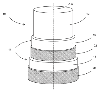
Power Cable
US Patent Application 20220334166
Published October 20, 2022
Inventor: Jos van Rossum, Bodegraven, Netherlands
Applicant: Prysmian S.p.A., Milan, Italy
A power cable includes a cable core, a jacket and an outermost semiconductor layer. The cable core includes at least one conductor, an insulating system thereof and at least one metallic screen. The jacket surrounds the cable core and includes an inner jacket layer and an outer jacket layer. The outermost semiconducting layer surrounds the outer jacket layer in direct contact thereto. The power cable further includes a test semiconducting layer radially external to the inner jacket layer, radially internal to the outer jacket layer and directly contacting them. A power cable system, and a jacket integrity testing method for a power cable are also provided.
Insulated Electric Wire, Coil and Producing Method for Same Coil
US Patent 11476024
Issued October 18, 2022
Inventors: Keisuke Fujito, Tokyo, Japan; Shohei Hata, Tokyo, Japan; Hiromitsu Kuroda, Tokyo, Japan; and Takayuki Tuji, Tokyo, Japan
Assignee: Hitachi Metals, Ltd., Tokyo, Japan
An insulated electric wire is composed of a conductor composed of a copper material and an electrical insulating layer provided on an outer periphery of the conductor. For the constituent conductor of the insulated electric wire, in an orientation intensity ratio obtained by X-ray diffraction of a transverse cross section of the conductor, an intensity in a [200] crystal orientation is higher than an intensity in a [111] crystal orientation.
Multi-Conductor Cable of Reduced Diameter and Contact Apparatus for Same
US Patent 11472303
Issued October 18, 2022
Inventor: Richard Habering, Cologne, Germany
Assignee: Igus GmbH, Cologne, Germany
An electrical multi-conductor cable comprising a plug-in connector, in particular a line with a charging plug for electric vehicles. The cable has a central cable core, a number of conductors which are arranged concentrically in relation to one another in a ring around the cable core and are composed of individual wires, and in each case one insulation between the conductors. According to the invention, the contact apparatus has two clamping shell parts which, on the inner side thereof, have a plurality of receptacles which are radially stepped from one another. In each case one contact body is received in the receptacles of a clamping shell part and makes contact with one of the concentric conductors. Each contact body has a channel shape with a longitudinal extent and a curved cross-sectional profile around an associated conductor. A closure connects the clamping shell parts and fastens said clamping shell parts in the closed position, wherein the clamping shell parts coaxially hold the contact bodies and press each contact body against the respectively associated concentric conductor for contact-making purposes.
Apparatus and Methods Using the Apparatus for Treating Metal Wire
US Patent Application 20220324003
Published October 13, 2022
Inventor: Geert de Kempe, Brugge, Belgium
Applicant: NV Bekaert SA, Zwevegem, Belgium
An apparatus for treating metal wire by multiple reverse bending and associated methods for using the apparatus are disclosed. The first roller has a first roller diameter, is followed by N−1 intermediate rollers with intermediate roller diameters and ends with an exit roller with an exit roller diameter. The exit roller is larger than the first roller and any one roller in the sequence of rollers has a roller diameter that is not smaller than the preceding roller in the sequence. The progressively larger diameters impose a well-controlled, gradually decreasing curvature to the wire resulting in a cast-controlled wire. By folding the wire path together, a compact arrangement is obtained accommodating the increasingly larger rollers. A method to operate the apparatus is also described that allows for an easy adjustment of the apparatus in function of wire thickness.
Copper-Coated Steel Wire, Stranded Wire, Insulated Electric Wire and Cable
US Patent Application 20220328210
Published October 13, 2022
Inventors: Takumi Akada, Osaka-shi, Japan; and Daigo Sato, Osaka-shi, Japan
Applicant: Sumitomo Electric Industries, Ltd., Osaka-shi, Japan
A copper-coated steel wire includes a core wire made of a steel and a coating layer that covers the outer peripheral surface of the core wire and is made of copper or a copper alloy. In a cross section perpendicular to the longitudinal direction of the core wire, the ten-point average roughness Rzjis of the outer peripheral surface of the core wire is 50% or more and 250% or less of the thickness of the coating layer.
Cable for Bicycle
US Patent Application 20220325472 A1
Published October 13, 2022
Inventor & Applicant: Yuan-Hung Wen, Chang Hua County, Taiwan
A cable for a bicycle is provided, including: an inner tube, a metal layer, a woven layer and an outer layer. The metal layer includes at least one metal wire disposed around an outer periphery of the inner tube. The woven layer is disposed around an outer periphery of the metal layer and includes a plurality of yarn threads interlaced with one another. The outer layer is disposed around an outer periphery of the woven layer, and the plurality of yarn threads are partially embedded radially within the outer layer.
Optical Fiber Unit and Optical Fiber Cable
US Patent Application 20220326467
Published October 13, 2022
Inventors: Akihisa Watanabe, Osaka-shi, Osaka, Japan; Masakazu Takami, Osaka-shi, Osaka, Japan; SATO; and Fumiaki Sato, Osaka-shi, Osaka, Japan
Applicant: Sumitomo Electric Industries, Ltd., Osaka-shi, Japan
An optical fiber unit includes: an optical fiber ribbon in which a plurality of optical fibers are arranged in parallel and connected to each other; a colored bundle tape longitudinally wrapped around an optical fiber ribbon bundle in which a plurality of the optical fiber ribbons are stranded together; and a colored bundle yarn spirally wound around the optical fiber ribbon bundle and the bundle tape.
Electrical Connection between and Electrical Conductor and a Contact Element
US Patent Application 20220328985
Published October 13, 2022
Inventor: Karl Fröschl, Herrnbaumgarten, Austria
Applicant: Gebauer & Griller Kabelwerke GmbH, Vienna, Austria
A method for producing an electrical connection between an electrical conductor, which includes a plurality of individual wires, and a contact element. The electrical conductor is arranged in a contact portion of the contact element, and the contact portion and the electrical conductor are subsequently pressed together so that the contact portion surrounds the electrical conductor. A a plurality of mutually spaced elongate welded connections between the contact portion and the electrical conductor are produced by laser irradiation of the contact portion, or by laser irradiation of the electrical conductor through an opening in the contact portion. The elongate welded connections extend in an irradiation direction from an irradiated region of the contact portion, or from an irradiated region of the electrical conductor, through an entire cross-section of the pressed electrical conductor to a region of the contact portion opposite to the irradiated region, such that the electrical conductor is connected to this area of the contact portion; and the irradiated regions are arranged in the form of a grid.
Optical Fiber Cable Production Method and Optical Fiber Cable
US Patent Application 20220326462
Published October 13, 2022
Inventors: Tomoaki Kaji, Sakura-shi, Japan; Akira Namazue, Sakura-shi, Japan; and Ken Osato, Sakura-shi, Japan
Applicant: Fujikura Ltd., Tokyo, Japan
An optical fiber cable production method includes: feeding a core including optical fibers; winding a reinforcing wrap around the core and forming an overlapping portion in which end portions of the reinforcing wrap overlap each other at a portion of the reinforcing wrap in a circumferential direction; and performing extrusion molding of a sheath on an outside of the reinforcing wrap. The overlapping portion extends in a longitudinal direction of the optical fibers. In the performing extrusion molding, a resin that forms the sheath is inserted into a portion of the overlapping portion.
Filling Composition for Optical Fiber Cables
US Patent 11466155
Issued October 11, 2022
Inventors: Gangwei Sun, Shanghai, China; XianMin Xu, Shanghai, China; Mohamed Esseghir, Lawrenceville, NJ, USA; Peng Gao, Shanghai, China; Youjun Wu, Shanghai, China; and Lingfeng Yu, Shanghai, China
Assignee: Dow Global Technologies LLC, Midland, MI, USA
A filling composition comprises (A) a mineral oil having a kinematic viscosity from 80 cSt to 100 cSt at 40°C.; (B) a styrene-ethylene/propylene diblock copolymer; and (C1) a propylene/ethylene copolymer having a weight average molecular weight (Mw) from 5000 to 200,000 or (C2) an ethylene/propylene copolymer having a weight average molecular weight (Mw) from 5000 to 200,000. The filling composition is used as a filling composition in a buffer tube.
Retained Adhesion of a Cable-Connector Using A Plasma Process
US Patent 11467356
Issued October 11, 2022
Inventors: Adra Smith Baca, Hickory, NC, USA; Linda Sue Baker, Addison, NY, USA; Ming-Huang Huang, Ithaca, NY, USA; Christine Marie Mahoney Fahey, Corning, NY, USA; and Wageesha Senaratne; Horseheads, NY, USA
Assignee: Corning Research & Development Corporation, Corning, NY, USA
The present disclosure relates to a plasma treatment (under atmospheric conditions or under vacuum conditions) of a jacketed cable comprising a cable jacket and a heat shrink tubing. The plasma treatment improves retention properties of an optical fiber cable assembly by imparting a permanent change on a polymer surface of the cable jacket by cross-linking, leading to eventual graphitization, that can result in a diffusion barrier layer at an interface of the cable jacket and the heat shrink tubing, which prevents or minimizes plasticizer migration and results in an environmental seal (e.g., a long-term water tight seal).
Electric Vehicle Charging Cable
US Patent Application 20220314822
Published October 6, 2022
Inventors & Applicants: Hyun Woong Kim, Suwon-si, Gyeonggi-do, South Korea; Jae Bok Lee, Gwanak-gu, Seoul, South Korea, Dong Kyun Yoo, Yongin-si, Gyeonggi-do, South Korea; and Uk Yeol Choi, Geumcheon-gu, Seoul, South Korea
The present disclosure relates to an electric vehicle charging cable, in which a cooling fluid is used to efficiently cool heat generated during charging of an electric vehicle, a thermally conductive material is added as well as the cooling fluid to improve cooling performance, thereby preventing damage to inner components due to heat, safety accidents such as fire are prevented and a diameter of the cable is minimized.
Rewindable Optical Fiber Cable
US Patent Application 20220317401
Published October 6, 2022
Inventors: Binod Balachandran, Gurgaon, India; Sudipta Bhaumik, Gurgaon, India; and Swapnil Sharma, Gurgaon, India
Applicant: Sterlite Technologies Limited, Gurgaon, India
A low fatigue rewindable optical fiber cable comprises a core having at least one optical transmission element, a dielectric armouring surrounding the core and a sheath surrounding the dielectric armouring. Particularly, the low fatigue rewindable optical fiber cable is characterized by a fatigue performance ratio (FPR) which is a ratio of a cross sectional area of the sheath and a cross sectional area of the dielectric armouring and is between 3 to 4.5 that enables at least 10 cyclic winds and unwinds carried out on a drum with a diameter of 40 times an outer diameter of the low fatigue rewindable optical fiber cable.
Combined Cable
US Patent Application 20220319736
Published October 6, 2022
Inventors: Zhiwei (Jack) Guo, Dongguan, China; and Hainan (Harlan) Lu, Dongguan, China
Applicant: Tyco Electronics (Shanghai) Co., Ltd., Shanghai, China
A combined cable includes at least two cable groups, each comprising at least one cable arranged side by side. Each cable group further comprises an adhesive layer wrapping a periphery of the at least one cable and having adhesion agent located on an outside of the adhesive layer. Each cable group further includes two coating layers, respectively adhered to a periphery of the adhesive layer of each cable group with the adhesion agent from upper and lower sides of the at least two cable groups. The coating layers located between adjacent two cable groups are detachably abutted together.
Corrugated Cable Dispenser
US Patent 11459205
Issued October 4, 2022
Inventor: Wayne Roussel, Mooreland, IN, USA
Assignee: Belden, Inc., St. Louis, MO, USA
The present disclosure describes methods of manufacture and implementations of cable storage and dispensing systems combining the advantages of reel-based systems and box-based systems. The present system may be manufactured entirely out of corrugated cardboard or similar materials, reducing expense and weight compared to systems with wood, plastic, or metal reels or flanges, and adding recyclability in a single paper-based waste stream. The system may dispense cable in the same manner as reel-based systems, reducing tangling and aiding installation and deployment compared to box-based systems that do not utilize reels or spools. The system does not require the use of reel stands or other external components and may be light and portable.
Apparatus for Unravelling Wire Ropes
US Patent Application 20220319743
Published October 6, 2022
Inventor: Franz Rieser, Bad Hofgastein, Germany
Applicant: Zeck GmbH, Schesslitz, Germany
The invention relates to an apparatus for unravel-ling wire ropes (3), which are made up of a complex of different materials, having a peeling device (1) with an opening (5), through which a core (9) of the wire rope (3) passes along a through-feed axis (D) and a through-feed direction (Z), while an outer portion (10) is separated, said peeling device (1) comprising a mandrel (4) through which the opening (5) passes axially, with at least one rotatable cutting wheel (12) being provided next to the mandrel (4), which wheel has on the circumference thereof at least one blade (13) and the axis of rotation (R) of which wheel is substantially transverse to the through-feed axis (D), characterized in that a cut-ting profile (6) of the blade (13) or a common cutting profile (6) of the blades (13) is concave in form.
Cable Insulation
US Patent 11462340
Issued October 4, 2022
Inventors: Mattias Berqvist, Gothenburg, Sweden; and Bernt-Åke Sultan, Stenungsund, Sweden
Assignee: Borealis AG, Vienna, Austria
The present invention relates to a wire or cable comprising a conductor coated with an insulation composition, wherein said insulation composition comprises: i) a polyethylene copolymer having a melting point of 105°C or less; and ii) a hindered amine light stabilizer (HALS) comprising at least one 2,2,6,6-tetramethyl-piperidinyl group present in an amount of 0.5 to 1.5 wt %.
Cable Sheath Material
US Patent 11460654
Issued October 4, 2022
Inventors: Fredrik Skärgård, Nasviken, Sweden; Jonas Ekstedt, Forsa, Sweden; Anders Lindroth, Hudiksvall, Sweden; and Roger Färlin, Ljusdal, Sweden
Assignee: Hexatronic Cables & Interconnect Systems AB, Gothenburg, Sweden
A cable assembly is provided, adapted to be installed into a duct by means of a combination of blowing and mechanical feeding. The cable assembly comprises at least one flexible signal transmitting member for transmitting optical signals, a first layer surrounding said at least one signal transmitting member such that at least one signal transmitting member is in touching contact with said first layer, and a second layer arranged outwardly of said first layer, said second layer being a non-thermoplastic layer comprising a non-thermoplastic, crosslinked polyethylene material. A method of producing the cable assembly is also disclosed.
Methods For Forming Cables with Shapeable Strength Members
US Patent 11454775
Issued September 27, 2022
Inventor: Christopher W. McNutt, Woodstock, GA, USA
Assignee: Superior Essex International LP, Atlanta, GA, USA
A method for forming a cable may include providing a strength member that includes a plurality of strength fibers positioned within a shapeable resin material. A shape of the strength member may be modified along its longitudinal length while twisting the strength member with one or more fiber optic components. The modified shape of the strength member may then be fixed within a desired operating temperature range of the cable, and a jacket may be formed around the strength member and the one or more optical fiber components.
Superconducting Power Cable
US Patent Application 20220301744
Published September 22, 2022
Inventors: Dag Willén; Klagshamn, Sweden; Carsten Thidemann, Jaegerspris, Denmark; and Martin Pitzer, Bonn, Germany
Applicant: NKT Cables Group A/S, Brøndby, Denmark
A superconducting power cable having: a former including: an axially stretchable core, and a plurality of elongated outer elements wound helically around the core, wherein the core includes a first material and the elongated outer elements include a second material thermally contracting less than the first material at the operating temperature of the superconducting power cable; and a superconducting conductor layer arranged around the former.
Electrical Cable for Vertical Applications
US Patent 11450455
Issued September 20, 2022
Inventors: Luca Giorgio Maria De Rai, Milan, Italy; Rosalba Orazi, Milan, Italy; and Marco Tedeschi, Milan, Italy
Assignee: Prysmian SpA, Milan, Italy
An electrical cable for vertical applications includes a core having a length L, a sheath surrounding the core and extending through the whole length L and a reinforcing jacket surrounding the sheath and in direct contact therewith. The reinforcing jacket is made of concentric layers including a first layer longitudinally extending from a first cable end (the proximal or upper cable end, in use) towards a second cable end (the distal or lower cable end, in use) substantially along the whole length L. The reinforcing jacket also includes at least one further layer longitudinally extending from the first cable end towards the second cable end for a length shorter than L. At least one layer of the reinforcing jacket is a circumferentially closed metal tube.
High Fiber Count Undersea Cable
US Patent Application 20220283397
Published September 8, 2022
Inventors: Marsha Ann Spalding, Hampton, NJ, USA; and Ralph J. Rue, Barnegat, NJ, USA
Applicant: Subcom, LLC, Eatontown, NJ, USA
Disclosed are approaches for forming a semiconductor device. In some embodiments, a method may include providing a patterned hardmask over a substrate, and providing, from an ion source, a plasma treatment to a first section of the patterned hardmask, wherein a second section of the patterned hardmask does not receive the plasma treatment. The method may further include etching the substrate to form a plurality of fins in the substrate, wherein the first section of the patterned hardmask is etched faster than the second section of the patterned hardmask.