
USPTO Wire & Cable Industry Patents for November 2021
United States Patents as compiled by the editors of Wire & Cable Technology International
System and Apparatus for Wire and Cable Packaging and Payoff
United States Patent 11,161,711
Issued November 2, 2021
Inventors: John L. Rhoads, The Colony, TX, USA; William T. Bigbee, Jr., Melissa, TX, USA; Troy D.
Skidmore, McKinney, TX, USA; and Karolina Zuraw, Richardson, TX, USA
Assignee: Encore Wire Corporation, McKinney, TX, USA
An apparatus for the transportation and payoff of coiled wire and cable, the apparatus comprising a
clamshell package, an inner void formed by the clamshell package, the inner void comprising a
compartment within for containing coiled wire and cable during transportation and payoff of the wire
and cable, a payoff port is coupled to the clamshell package, wherein the coiled wire and cable is
extracted from the clamshell package through the payoff port on an axis substantially similar to the
axis of the extracted wire and cable, and wherein the payoff port extends from the clamshell package
through the coiled wire and cable.
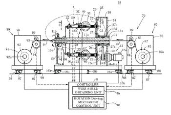
Wire Stranding Apparatus and Method for Manufacturing Stranded Wire
United States Patent 11,155,938
Issued October 26, 2021
Inventor: Nao Shibuya, Nagasaki, Japan
Assignee: Nittoku Co., Ltd., Saitama, Japan
A wire stranding apparatus, comprising: a core wire moving mechanism configured to move a core wire in an axial direction; a spool configured to feed a wound wire by rotation; a revolving mechanism
configured to revolve the spool about the core wire; a rotation driving mechanism configured to feed
the wire by rotating the spool, the wire fed from the spool being spirally wound on an outer periphery
of the core wire moving in the axial direction by revolution of the spool; and a control device including
a wire speed obtaining unit configured to obtain a speed of the wire to be wound on the core wire and
a rotation driving mechanism control unit configured to control the rotation driving mechanism such
that the speed of the wire obtained by the wire speed obtaining unit has a predetermined value.
Method of Removing Foil Shield from Cable
United States Patent 11,159,003
Issued October 26, 2021
Inventors: Matthew Steven Houser, Hummelstown, PA, USA; Joseph Stachura, Lebanon, PA, USA; and
Christopher John Gavlak, Mechanicsburg, PA, USA
Assignee: TE Connectivity Corporation, Berwyn, PA, USA
A method of removing a foil shield from a cable. The method includes: positioning the cable proximate
a heating source; heating the foil shield in a designated area to weaken the foil shield; and removing
an outer insulation of the cable and the foil shield after the foil shield has been heated.
Loose Tube Cable with Embedded Strength Member
United States Patent 11,156,792
Issued October 26, 2021
Inventors: Kishore Chandra Sahoo, Aurangabad, India; Sravan Kumar, Aurangabad, India; Pavan
Kumar Moturu, Aurangabad, India; Atul Mishra, Aurangabad, India; and Kavya Chintada, Aurangabad,
India
Assignee: Sterlite Technologies Limited, Gurgaon, India
The present disclosure provides an optical fiber cable (100). The optical fiber cable (100) includes a
plurality of optical fibers ribbons (102) lying substantially along a longitudinal axis (116) of the optical
fiber cable (100). Further, the optical fiber cable (100) includes a first layer (104) surrounding the
plurality of optical fibers ribbons (102). Furthermore, the optical fiber cable (100) includes a second
layer (106) surrounding the first layer (104). Furthermore, the optical fiber cable (100) includes a third
layer (108) surrounding the second layer (106). Moreover, the optical fiber cable (100) includes a fourth
layer (140) surrounding the third layer (108). The first layer (104) is a water blocking tape. The third
layer (108) is sandwich of water blocking material and ECCS steel tape. Moreover, the optical fiber
cable (100) includes two pairs of strength members (112a-b; 112c-d) embedded inside the second
layer (106).
Method for Removing Insulation from Inner Conductors of a Cable, and Stripping Device
United States Patent 11,159,002
Issued October 26, 2021
Inventor: Zoran Calic, Kriens, Switzerland
Assignee: Komax Holding AG, Dierikon, Switzerland
A method for removing insulation from inner conductors of a cable having a first section with a cable
sheath removed and a second section with the cable sheath not removed utilizes a stripping device to
perform the following steps: inserting the first section between a first rotatable roller and a second
rotatable roller of the stripping device; moving the first roller and/or the second roller toward each
other to clamp the first section between the rollers; moving the cable in a first direction that moves
the second section away from the rollers; moving the cable in a second direction opposite the first
direction that moves the second section toward the rollers; moving stripping blades toward the first
section to cut into the insulation of the inner conductors; and moving the cable in the first direction to
remove at least part of the insulation from the inner conductors.
Capacitive Power Transmission Cable
United States Patent 11,158,440
Issued October 26 2021
Inventors: Mansour Salehi-Moghadam, Surrey, Great Britain; Gareth O’Brien, County Meath, Ireland;
Charles Lucas-Clements, Surrey, Great Britain; and Dominic Quennell, Greater London, Great Britain
Assignee: Enertechnos Holdings Limited, Surrey, Great Britain
A capacitive power transmission cable (1) having at least two sets of conductive strands (2) and the
strands of the sets are distributed in a transverse cross-section of the cable, whereby the two sets are
in capacitive relation to each other, wherein preferably, the capacitance is at least 10 nF/m.
Electric Cable Having Improved Thermal Conductivity
United States Patent 11,158,437
Issued October 26, 2021
Inventors: Gabriele Perego, Milan, Italy; Christelle Mazel, Ruy, France; Dimitri Charrier, Ecully, France;
and Daphne Merle, Lyons, France
Assignee: Nexans, Courbevoie, France
The invention relates to a cable comprising at least one electrically insulating layer obtained from a
polymer composition comprising at least one polypropylene-based thermoplastic polymer material
and at least one inorganic filler chosen from silicates, boron nitride, carbonates and a mixture thereof,
and to a process for preparing said cable.
Flexible Crosslinked Cable Insulation and Methods for Making Flexible Crosslinked Cable Insulation
United States Patent 11,155,693
Issued October 26, 2021
Inventors: Bharat I. Chaudhary, Princeton, NJ, USA; Juan C. Tuberquia, Manvel, TX, USA; Rennisha Wickham, Pearland, TX, USA; Philip P. Fontaine, Pearland, TX, USA; Colin Li Pi Shan, Pearland, TX, USA; Morgan M. Hughes, Angleton, TX, USA; Jan Bazen, Hoek, Netherlands; Edward O. Madenjian, Lake
Jackson, TX, USA; and Gregory J. Brennan, Angleton, TX, USA
Assignee: Dow Global Technologies LLC, Midland, MI, USA
Crosslinkable polymeric compositions comprising (a) 10 to 99 weight percent of an ethylene-based
interpolymer having the following properties: (i) a density of 0.93 g/cm3 or less, (ii) a high-shear
viscosity (V100) at 190°C and 10% strain of 1200 Pa-s or less, and (iii) a shear thinning ratio (V0.1/ V100)
at 190°C and 10% strain of at least 8; and (b) 0 to less than 10 weight percent of a filler, where the
ethylene-based interpolymer is not prepared in a high-pressure reactor. Such crosslinkable polymeric
compositions may be employed as insulation layers in flexible power cables.
Fire Rated Radio Frequency Cable
United States Patent 11,152,138
Issued October 19, 2021
Inventors: Asaad Elsaadani, Meriden, CT, USA; Mihirraj Joshi, Middletown, CT, USA; Joel Cacopardo, Hamden, CT, USA; Erhard Mahlandt, Hannover, Germany; Thomas McKeon, Wallingford, CT, USA; and
Yin-Shing Chong, Middletown, CT, USA
Assignee: Nokia Shanghai Bell Co., Ltd., Shanghai, China
A coaxial cable (10) includes an outer barrier (12, 14, 16) that seals the coaxial cable from air and
protects the cable’s conductors (18, 20) form oxidation in a fire. Such an outer protective barrier may
include a fire-retardant tape. A dielectric (22) separates the conductors and may comprise a ceramic
(23) embedded in a dielectric material (25) or ceramic beads in a braided ceramic mesh.
Communications Cable with Triboelectric Protection
United States Patent 11,152,137
Issued October 19, 2021
Inventors: Ronald A. Nordin, Naperville, IL, USA; and Royal O. Jenner, Frankfort, IL, USA
Assignee: Panduit Corp., Tinley Park, IL, USA
A communications cable has a plurality of twisted pairs of insulated conductors, metal foil tape
between the twisted pairs and a cable jacket are disclosed. The metal foil tape can include a substrate,
a metal layer on the substrate and a triboelectric coating on at least the metal layer of the metal foil
tape. The triboelectric coating has a charge affinity closer to a charge affinity of the insulated
conductors than a charge affinity of the metal layer to prevent charge build up between the
conductors and the metal foil tape.
Assembled Wire, Method of Manufacturing Assembled Wire and Segment Coil
United States Patent 11,145,436
Issue October 12, 2021
Inventors: Keisuke Ikeda, Tokyo, Japan; Keiichi Tomizawa, Tokyo, Japan; Daisuke Muto, Tokyo, Japan;
and Hideo Fukuda, Tokyo, Japan
Assignee: Essex Furukawa Magnet Wire Japan Col, Ltd., Tokyo, Japan
An assembled wire has a substantially rectangular cross section and is formed by assembling a
plurality of strands. Each strand has a conductor portion and a strand insulating layer covering the
conductor portion. At least a part of the assembled plurality of strands in the longitudinal direction is
covered with an outer insulating layer. The strand is formed as follows. First, the strand insulating
layer is coated on the outer periphery of the conductor portion. A large number of voids are formed in
a resin constituting the strand insulating layer. From this state, the strand is formed, for example, by
collapsing the strand insulating layer by heating and pressurizing. At this time, it is possible to
uniformly collapse the strand insulating layer by crushing the internal voids. Therefore, the voids in
the strand are crushed and flattened in the thickness direction of the strand insulating layer over the
entire periphery.
Steel Wire for Spring
United States Patent 11,143,257
Issued October 12, 2021
Inventors: Takafumi Uwano, Itami, Japan; Takeoshi Sasaki, Itami, Japan; and Takao Yamazaki, Itami, Japan
Assignee: Sumitomo Electric Industries, Ltd., Osaka, Japan
A steel wire for a spring includes a steel wire that has Ca or Na adhered thereto in an amount of 0.2
g/m2 or less. The steel wire has an oxide film on a surface thereof, and the oxide film has a thickness
of, for example, from 2.0 to 20 μm.
Method of Testing a Fire Resistant Coaxial Cable
United States Patent 11,145,440
Issued October 12, 2021
Inventor: William E. Rogers, Danville, CA, USA
Assignee: American Fire Wire, Inc., Minden, NV, USA
Methods of testing and installing fire-resistant coaxial cables are described. The dielectric between the
coax cable’s central conductor and outer coaxial conductor ceramify under high heat, such as those
specified by common fire test standards (e.g., 1850°F/1010°C for two hours). The dielectric can be
composed of ceramifiable silicone rubber, such as that having a polysiloxane matrix with inorganic
flux and refractory particles. Because thick layers of uncured ceramifiable silicone rubber deform
under their own weight when curing, multiple thinner layers are coated and serially cured in order to
build up the required thickness. A sacrificial sheath mold is used to hold each layer of uncured
ceramifiable silicone rubber in place around the central conductor while curing. The outer conductor
can be a metal foil, metal braid, and/or corrugated metal. Another layer of extruded ceramifiable
silicone dielectric or an outer wrap of ceramic fiber yarn surrounds the outer conductor and continues
to insulate it from the outside if a low smoke zero halogen jacket burns away.
Flexible Cable with Structurally Enhanced Conductors
United States Patent 11,145,433
Issued October 12, 2021
Inventor: Richard Temblador, Temecula, CA, USA
Assignee: Southwire Company, LLC, Carrollton, GA, USA
In an electrical cable of the type having an outer sheath enclosing a conductor assembly comprising a
plurality of insulated conductors disposed within a binder, the binder having a crush resistance for
protecting the insulated conductors, an improvement in which a strength enhancer is applied such
that the binder can be removed without decreasing a crush resistance of the electrical cable.
Steel Wire Rope, Elevator Provided with Steel Wire Rope, Lubricant for Steel Wire Rope, and Use of
Lubricant for Lubricating the Steel Wire Rope
United States Patent 11,136,713
Issued October 5, 2021
Inventor: Raimo Pelto-Huikko, Helsinki, Finland
Assignee: Krone Corporation, Helsinki, Finland
A wire rope is disclosed that comprises metal wires, preferably steel wires, as a load-bearing material, which rope comprises at least one or more strands laid from said metal wires and which rope is lubricated with a lubricant. Another object is the use of the aforementioned lubricant for lubricating a
steel rope. The lubricant comprises at least oil and powder substance, which powder substance
comprises at least particles whose hardness is greater than 4 on the Mohs scale. A traction sheave
elevator comprising such a wire rope as a suspension rope is disclosed, too.
Wire Rod Having Excellent Low Temperature Impact Toughness and Manufacturing Method
United States Patent 11,136,637
Issued October 5, 2021
Inventors: Hyong-Jik Lee, Pohang-si, South Korea; and Young-Soo Chun, Pohang-si, South Korea
Assignee: POSCO, Pohang-si, South Korea
Disclosed are a steel wire rod having excellent low temperature impact toughness and a manufacturing method therefor. The steel wire rod having excellent low temperature impact
toughness according to an embodiment of the present invention contains, by weight %, carbon (C):
0.40-0.90%, silicon (Si): 0.5-1.0%, manganese (Mn): 11-25%, copper (Cu): 1.0- 3.0%, phosphorus (P):
0.020% or less, sulfur (S): 0.020% or less, aluminum (Al): 0.010-0.050%, nitrogen (N): 0.0010- 0.0050%
and the remainder being Fe and unavoidable impurities. The steel wire rod has a microstructure which
contains an austenite phase having an area fraction of 95% or more, and a volume fraction of a
deformation twin formed in an austenite grain is 1% to 8%. Therefore, it is possible to provide a steel wire rod having excellent low temperature impact toughness used in industrial machines or automobile parts, etc.
Ground Wire with Optical Fibers
United States Patent 11,131,823
Issued September 28, 2021
Inventors: Alexander Smilgevich, Perm, Russia; Alexey Shabalin, Perm, Russia; Sergey Yakovlev, Perm,
Russia; and Michael L Riddle, Rome, GA, USA
Assignee: Incab, LLC, Perm, Russia
A ground wire with optical fibers is disclosed. The ground wire includes twisted optical modules in the
form of plastic tubes that accommodate freely placed optical fibers and water-blocking gel, wherein water-blocking tape applied to twisted optical modules, which are enclosed in a steel tube, coated with
an aluminum sheath. The aluminum sheath is helically wrapped with lays of wire. The technical result
is provided by increased air tightness of the optical core and permissible crushing stresses.
Superconducting Wire, Superconducting Coil, MRI and NMR
United States Patent 11,127,514
Issued September 21, 2021
Inventors: Hideki Tanaka, Tokyo, Japan; Kazuya Nishi, Tokyo, Japan; Takaaki Suzuki, Tokyo, Japan; and
Yota Ichiki, Tokyo, Japan
Assignee: Hitachi, Ltd., Tokyo, Japan
It is an object of the present invention to provide an MgB2 wire helping to achieve compatibility
between the ease with which superconducting connection is affected and thermal stability. A
superconducting wire according to the present invention includes: an elemental wire formed of MgB2;
and a first metal not reacting with Mg. In a section orthogonal to the longitudinal direction of the
superconducting wire, the region extending from the center of the superconducting wire to the
installation position of the elemental wire is formed by the elemental wire and the first metal.
Wire for Medical Device and Medical Device
United States Patent 11,123,525
Issued September 21, 2021
Inventors: Naoyasu Hanamura, Tokyo, Japan; Hiroaki Kasai, Tokyo, Japan; Hisamitsu Kuwabara, Tokyo,
Japan; Kohei Shiramizu, Kawasaki, Japan; and Takuya Fujihara, Tokyo, Japan
Assignee: Olympus Corporation, Tokyo, Japan
A wire for a medical device includes a wire body and a solid lubrication film. The wire body has an
outer circumferential layer formed of a plurality of metal strands that are twisted with each other. The
solid lubrication film is formed at least on outside exposed surfaces of the plurality of metal strands. When a virtual circle as a smallest circle enclosing the outer circumferential layer is assumed in a cross
section perpendicular to a central axis of the wire body, a part of an outer edge of the solid lubrication
film of the cross section is inside the virtual circle and a cross-sectional area of the solid lubrication
film in the cross section satisfies A/B>0.7 where A is a size of a portion outside the virtual circle and B
is a size of a portion inside the virtual circle.
Apparatus and Method for Spooling Wire
United States Patent 11,117,780
Issued September 14, 2021
Inventors: John L. Rhoads, The Colony, TX, USA; and Kevin D. Rodgers, Frisco, TX, USA
Assignee: Encore Wire Corporation, McKinney, TX, USA
A reel apparatus comprising a pipe; an outer flange assembly comprising two outer support walls
connected to the pipe and wherein each outer support wall comprises an inner wall and an outer wall;
an inner flange assembly comprising two inner support walls, wherein the inner flange assembly is
rotated relative to the outer flange assembly and the pipe and wherein each inner support wall
comprises an inner wall and an outer wall; and a motor assembly connected to the inner flange
assembly and outer flange assembly, wherein the motor assembly is physically connect to the outer
flange assembly and wherein the motor assembly is rotationally connected to the inner flange
assembly.
Wire and Cable Package
United States Patent 11,117,737
Issued September 14, 2021
Inventors: Juan Alberto Galindo Gonzalez, Powder Springs, GA, USA; Richard Mike Temblador,
Carrollton, GA, USA; Laurentiu Dan Dragomir, Atlanta, GA, USA’ Allan W. Daniel, Woodland, AL, USA;
and James Phillip Tuggle, Carrollton, GA, USA
Assignee: Southwire Company, LLC, Carrollton, GA, USA
Consistent with embodiments of the invention, a cable package may be provided. The cable package may comprise a cable and a chamber. The cable may comprise a winding and at least one free end.
The chamber may define an internal volume containing the cable. The chamber may comprise a
continuous opening. The continuous opening may comprise at least one surface arranged to apply
pressure to a portion of the cable located proximate to the continuous opening.
Apparatus and Method for a Free-Spinning Wire Dispensing Reel
United States Patent 11,111,100
Issued September 7, 2021
Inventors: William T. Bigbee, Jr., Melissa, TX, USA; and John L. Rhoads; John, The Colony, TX, USA
Assignee: Encore Wire Corporation, McKinney, TX, USA
An apparatus and method for dispensing wire or cable from a reel assembly. In one embodiment, the
apparatus comprises an inner flange assembly and an outer flange assembly. The inner flange
assembly is capable of freely rotating relative to the outer flange assembly for dispensing wire from
any surface. In another embodiment, the apparatus includes an inner flange assembly, an outer flange
assembly and an external bay. The inner flange assembly is capable of freely rotating relative to the
outer flange assembly and the external bay. The external bay is capable of freely rotation relative to
the outer flange assembly and the inner flange assembly. In another embodiment, wire is dispensed
from a reel assembly comprising an inner flange assembly and an outer flange assembly. In yet
another embodiment, wire is dispensed from a reel assembly comprising an inner flange assembly, an
outer flange assembly and an external bay.