
USPTO Wire & Cable Industry Patents for March/April 2022
United States Patent and Trademark Office (USPTO) as compile by the editors of Wire & Cable Technology International
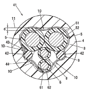
Composite Cable and Composite Harness
United States Patent 11,264,148
Issued March 1, 2022
Inventors: Yoshikazu Hayakawa, Tokyo, Japan; Tomoyuki Murayama, Tokyo, Japan; Hirotaka Eshima,
Tokyo, Japan; Fumihito Oka, Tokyo, Japan; and Takahiro Futatsumori, Tokyo, Japan
Assignee: Hitachi Metals, Ltd., Tokyo, Japan
A composite cable includes a pair of first electric wires, a twisted pair wire formed by twisting a pair of
second electric wires having a smaller outer diameter than the first electric wires, a tape member wound
into a spiral around an assembly that is formed by twisting the pair of first electric wires and the twisted
pair wire together and a sheath covering an outer periphery of the tape member. The tape member and
the sheath include an inwardly projecting part formed in a spiral along a cable longitudinal direction and
formed so as to enter inward at least one of a valley part between the two first electric wires and valley
parts between the first electric wires and the twisted pair wire. The inwardly projecting part has a
projecting length of not less than 3% of an outer diameter of the first electric wires.
Wire Rope with Resin Wire, Resin Wire Winding Die and Method for Producing Wire Rope with Resin Wire
United States Patent 11,261,564
Issued March 1, 2022
Inventor: Yukihiro Shibao, Hokkaido, Japan
Assignee: Riken Kogyo Inc., Hokkaido, Japan
Provided is a wire rope with resin wire including a wire rope body in which a plurality of strands are
twisted together, and at least one resin wire spirally wound around the wire rope body along a recess
between the strands. Strand grooves into which the strands can fit and a resin wire groove into which the
resin wire can fit are formed spirally along the twist of the wire rope with resin wire, in a winding hole of
a resin wire winding die used for winding the resin wire around the wire rope body. As a result, the resin
wire can be easily and reliably mounted on the wire rope body and a wire rope with resin wire can be
thus produced.
Multi Loose Tube Ribbon Cable
United States Patent 11,262,522
Inventors: Sravan Kumar, Maharashtra, India; Kishore Sahoo, Maharashtra, India; Kavya Chintada,
Maharashtra, India; Venkatesh Murthy, Maharashtra, India; Atul Mishra, Maharashtra, India; Pavan
Moturu, Maharashtra, India; and Kangabam Tenzing, Maharashtra, India
Assignee: Sterlite Technologies Limited, Aurangabad, India
The present disclosure provides an optical fiber cable. The optical fiber cable includes at least one optical
fiber ribbon stack In addition the at least one optical fiber ribbon stack includes a plurality of stacked fiber ribbon stack. In addition, the at least one optical fiber ribbon stack includes a plurality of stacked
ribbons. Further, each ribbon of the plurality of stacked ribbons includes a plurality of optical fibers. The
plurality of optical fibers includes edge fibers. The edge fibers are defined as the at least one optical fiber
having a mach number of at most 7.2 disposed at a first end and a second end of a first ribbon and a last
ribbon of the plurality of stacked ribbons.
Wire Rod Rolling Roller and Gap Adjustment Device Thereof
United States Patent 11,260,438
Issued March 1, 2022
Inventor: Hee Keun Cho, Andong-si, South Korea
Assignee: Andong National University Industry-Academic Cooperation Foundation, Andong-si, South
Korea
A wire rod rolling roller is disclosed. In one aspect, the wire rod rolling roller includes upper and lower
rollers spaced apart from each other and configured to roll a wire rod passing therebetween and upper
and lower drive shafts fixedly extending through the centers of the upper and lower rollers, respectively,
and configured to rotate the upper and lower rollers. The wire rod rolling roller also includes upper and
lower bearing housings respectively disposed on one side of the upper drive shaft and one side of the
lower drive shaft and configured to support the upper and lower drive shafts. The wire rod rolling roller
further includes a journal bearing inserted into the upper and lower bearing housings and in surface
contact with the upper and lower drive shafts to minimize fiction and a gap adjustment device configured
to adjust a gap between the upper and lower rollers.
Electric Cable with Improved Temperature Ageing Resistance
United States Patent 11,257,607
Issued February 22, 2022
Inventors: Christian Koelblin, Meximieux, France; Melek Maugin, Chassagny, France; Gabriele Perego,
Milan, Italy; and Valery Alcaraz, Saint-Fons, France
Assignee: Nexans, Courbevoie, France
An electric cable has at least one semi-conductive layer obtained from a polymer composition having at
least one polypropylene- based thermoplastic polymer material, at least one first antioxidant and at least
one metal deactivator.
Flame Retardant Fiber Optic Cable with Halogen Free Sheath for Blowing Applications
United States
Patent 11,256,052
Issued February 22, 2022
Inventors: Michael Alexander Heinz, Berlin, Germany; and Ravinder Kumar Kinnera, Berlin, Germany
Assignee: Corning Research & Development Corporation, Corning, NY, USA
Embodiments of the disclosure relate to an optical fiber cable. The optical fiber cable includes a subunit
having a first interior surface and a first exterior surface. The first interior surface defines a central bore
along a longitudinal axis of the optical fiber cable. At least one optical fiber is disposed within the central
bore of the subunit, and a plurality of strengthening yarns is disposed around the subunit. A cable sheath
disposed around the plurality of strengthening yarns. The cable sheath has a second interior surface and
a second exterior surface. The second exterior surface defines an outermost surface of the optical fiber
cable. The cable sheath includes from 55% to 68% by weight of a mineral-based flame retardant additive
and from 35% to 45% by weight of a polymer blend. The polymer blend includes a co-polyester or copolyether and a polyolefin or a polyolefin elastomer.
Automatic Wire Spooling Control
United States Patent 11,254,550
Issued February 22, 2022
Inventor: Randolph Scott Coles, Spring, TX, USA
Assignee: Halliburton Energy Services, Inc., Houston, TX, USA
Systems and methods can be used in connection with a wellbore environment for automatically
controlling wire being spooled around a drum. A system comprising a spooler, a sensor assembly and a
communication link can be used to adjust the position of wire being spooled around a drum. A first
motor can control the spooler and a second motor can control the sensor assembly. The spooler can be
positioned to control spooling of wire around the drum as the drum rotates to reel in wire. The sensor
assembly can be configured to detect a distance between the sensor assembly and the wire being
spooled. A communication link can communicatively couple the sensor assembly with the first motor and
the second motor to control movement of the spooler and the sensor assembly relative to the drum
based on the distance detected by the sensor assembly.
Cable with Aerogel Dielectric
United States Patent 11,250,974
Issued February 15, 2022
Inventor: Jason Wong, Aurora, CO, USA
Assignee: Fractal, Inc., Aurora, CO, USA
The present invention is a cable made from a braided polyethylene terephthalate cable sleeve. Inside the
cable sleeve is a sequence of four shielding layers: a braided copper wire layer, a braided silver-plated
copper wire layer and two braided carbon fiber layers. Within the fourth shielding layer is a
polytetrafluoroethylene inner sleeve containing a particulate aerogel dielectric, with an approximate
particle diameter from 2 μm to 1.2 mm, and a conductive metal core with a mirror polish.
Optical Fiber Cable and Manufacturing Method of Optical Fiber Cable United States Patent 11,249,272
Issued February 15, 2022
Inventors: Fumiaki Sato, Osaka, Japan; and Kuushin Ryan, Osaka, Japan
Assignee: Sumitomo Electric Industries, Ltd., Osaka, Japan
An optical fiber cable includes: a plurality of ribs formed along a longitudinal direction of a cable; and a
slot core in which a slot grove for housing an optical fiber ribbon is formed between the ribs. In the slot
groove, a plurality of optical fiber ribbons is bundled and a plurality of subunits whose periphery is
wound with a bundle material are provided, and the bundle materials between the plurality of subunits
are bonded to each other.
Electric Power Transmission Cable
United States Patent 11,250,970
Issued February 15, 2022
Inventors: Martin Krajcovic, Trnava, SK Slovakia; Wim Van Haver, Aalter, Belgium; and Christophe
Degraer, Merelbeke, Belgium
Assignee: NV Bekaert SA, Zwevegem, Belgium
An electric power transmission cable comprises electric power conductors and a plurality of parallel
spiraled armoring wires. The electric power transmission cable comprises along its length a first section
(I), a second section (III) and a transition section (II). The transition section (II) is provided between the first
section (I) and the second section (III). The plurality of parallel spiraled armoring wires in the first section
(I) comprises or consists out of first armoring wires (121). The first armoring wires (121) are carbon steel
wires comprising a metallic corrosion resistant coating. At least part of the plurality of parallel spiraling
armoring wires in the second section (III) comprise austenitic steel wires (123). In the transition section
(II), ends of first armoring wires (121) are individually welded to ends of austenitic steel wires (123) of the
second section (III). The transition section (II) starts at the first weld (137) between a first armoring wire
(121) and an austenitic steel wire (123). The transition section (II) ends at the last weld (130) between a
first armoring wire (121) and an austenitic steel wire (123). The transition section (II) is at least 10 m long.
Wire, in Particular for a Stranded Wire
United States Patent 11,248,340
Issued February 15, 2022
Inventors: Yucel Sahiner, Nuremberg, Germany; and Markus Schill, Munich, Germany
Assignee: Leoni Kabel GmbH, Roth, Germany
A wire (10) is disclosed. Said wire (10), when viewed in cross-section, has at least one first portion (12) and
at least one second portion (14) that are interconnected by a third portion (16) in which the wire (10) has
a reduced cross-section.
Insulated Wire, Method of Producing Insulated Wire, Coil, Rotating Electrical Machine and Electrical or Electronic Equipment
United States Patent 11,232,885
Issued January 25, 2022
Inventors: Kenji Fujimori, Tokyo, Japan; and Makoto Oya, Tokyo, Japan
Assignee: Essex Furukawa Magnet Wire Japan Co., Ltd., Tokyo, Japan
An insulated wire having at least one layer of coating of the wire, comprising a thermosetting resin layer,
at the outer periphery of a conductor, wherein the thermosetting resin layer is comprised of
thermosetting resin layers having a laminated structure formed by coating and baking a thermosetting
resin varnish; and wherein, in said laminated structure, an innermost layer having contact with the
conductor comprises a thermosetting resin having an imide bond and is a layer having an average
cothickness of more than 5 μm and 10 μm or less; a method of producing the insulated wire; a coil; a
rotating electrical machine; and an electrical or electronic equipment.
Integrated Systems Facilitating Wire and Cable Installations
United States Patent 11,228,163
Inventors: John R. Carlson, Newnan, GA, UAS; David Brian McCardel, Marietta, GA, USA; Davvid A. Cooper,
Douglasville, GA, USA; David Mercier, Carrollton, GA, USA; Philip Sasse, Douglasville, GA, USA; Allan W.
Daniel, Woodland, AL, USA; Timothy M. Andrea, Douglasville, GA, USA; Juan Alberto Galindo Gonzalez,
Powder Springs, GA, USA; and Timmothy R. Bardin, Carrollton, GA, USA
Assignee: Southwire Company, LLC, Carrollton, GA, USA
Pulling eyes are provided with integrated wiring systems suitable for installing conductors or cables. The
pulling eyes may include body portions that define interior cavities that are sized to snugly engage
outside portions of the conductors or cables. The body portions are sized to be deformably crimped onto
the outside portions of the conductors or cables. The pulling eyes may also include head portions joined
to the body portions, with the head portions defining apertures for receiving a strength member for
installing the conductors or cables. These apertures place the interior cavities in communication with the
exteriors of the pulling eyes.
Electric Cable
United States Patent 11,222,737
Issued January 11, 2022
Inventors: Christoph Studer, Gretzenbach, Switzerland; and Geraldine Studer, Gretzenbach, Switzerland
Assignee: Studer Aeronautical AG, Daniken, Switzerland
An electric cable for supplying power to aircrafts, rail vehicles, motor vehicles, ships or other devices is a
single or multi-conductor cable and includes one or more current conductors with at least one insulation.
A single or multi-layer outer casing is distributed over the periphery and is associated with the outwardly
protruding reinforcing elements. The reinforcing elements are in the form of cooling ribs protruding
preferably over the entire periphery of the cable and enable the surface of the cable to be increased and
as a result, improve heat dissipation. The projecting reinforcing elements considerably reduce the risk of
burning when the current conductors heat up and also to protect the cable against abrasion. The
invention also relates to a plug for the electric cable.
Motor Vehicle Charging
Cable United States Patent 11,220,188
Issued January 11, 2022
Inventors: Raoul Heyne, Wiernsheim, Germany; Jari Roenfanz, Muehlacker, Germany; and David Koehler,
Bietigheim-Bissingen, Germany
Assignee: Porsche AG, Dr. Ing. h.c. F., Stuttgart, Germany
A motor vehicle charging cable for DC voltage charging of an electrical energy store of a motor vehicle
has a cable sheath that encloses conductors, such as first and second cooling-fluid-cooled electrical
conductor for first and second DC voltage phases, a ground conductor or equipotential bonding
conductor and/or at least one control conductor. Shaped elements are arranged between the cable
sheath and the conductors at positions of the motor vehicle charging cable that are fixed in mounts. The
shaped elements guide, clamp and restrict a relative movement between the conductors. The cable
sheath restricts a relative movement between the conductors between those positions at which the
motor vehicle charging cable is fixed in mounts
motor vehicle charging cable is fixed in mounts.
Electrical Cable
United States Patent 11,217,918
Issued January 4, 2022
Inventors: James G. Vana, Jr, Cedar Park, TX, USA; Alexander Barr, Austin, TX, USA; and Richard J. Scherer,
Austin, TX, USA
Assignee: 3M Innovative Properties Company, St. Paul, MN, USA
An electrical cable (1000) including a plurality of substantially parallel insulated conductors (100) is
described. Each insulated conductor (100) includes an electrically conductive inner conductor (200) coextensive and covered with an insulating layer (300). At least a portion of a periphery of each insulated
conductor (100) may be encompassed by a substantially cothickness extensive electrically conductive
shield (400). For each insulated conductor (100), portions of the insulating layer (300) are removed from
the top side (1200) of the cable (1000) to expose a portion of the inner conductor (200) of the insulated
conductor (100). The insulated conductor (100) is adapted to mate with an electrically conductive mating
conductor (500) at the exposed portion (210) of the inner conductor (200).
Optical Fiber Cable
United States Patent 11,215,780
Issued January 4, 2022
Inventors: Masatoshi Ohno, Sakura, Japan; Kouji Tomikawa, Sakura, Japan; Ken Osato, Sakura, Japan;
Hiroaki Tanioka, Tsukuba, Japan; Shigekatsu Tetsutani, Tsukuba, Japan; Yohei Endo, Tsukuba, Japan; and
Yuta Maruo, Tsukuba, Japan
Assignees: Fujikura Ltd., Tokyo, Japan; and Nippon Telegraph and Telephone Corporation, Tokyo, Japan
An optical fiber cable includes: a cable body having a core and an inner sheath that accommodates the
core; a reinforcing sheet that surrounds the cable body; an outer sheath that accommodates the cable
body and the reinforcing sheet; and an outer ripcord that is embedded in the inner sheath. The inner
sheath includes a projection that projects outwardly in a radial direction of the optical fiber cable. At least
part of the outer ripcord is disposed inside the projection.