
Patents for May/June 2024
Wire & Cable Industry Patents as compiled from the United States Patent and Trademark Office (USPTO) for May 2024
Cable Containing LED Light Strip Driven by Induced Current
US Patent 11965628
Published April 23, 2024
Inventors: Lei Zong, Nantong, China; and Chunyan Liu, Nantong, China
Assignee: Shanghai Lanhao Jiangsu Electric Co., Ltd., Nantong, China
A cable containing an LED (Light Emitting Diode) light strip driven by an
induced current is provided. The cable includes an LED light strip, a cable
core and an outer protection layer covering the cable core and the LED light
strip. The cable core includes at least one power wire core. The LED light
strip includes a coil block and an LED chip which are connected in series to
form a closed loop. The coil block generates an induced potential under the
action of an alternating magnetic field generated after the power wire core
is powered on. The LED chip is lightened by the induced potential. The outer
protection layer is made of a light-transmitting material.
Apparatus for Cutting, Centering or Retaining a Cable in a Stripping Head and Cable-Stripping Device
US Patent 11967807
Published April 23, 2024
Inventors: Willi Blickenstorfer, Stallikon, Switzerland; and Raphael Deschler,
Oberhofen, Switzerland
Assignee: Schleuniger AG, Thun, Switzerland
The present invention relates to an apparatus (100, 200, 300) for cutting,
centering or holding a cable in a stripping head, comprising a first toothed
belt wheel (1) and a second toothed belt wheel (2), which are rotatable
coaxially and synchronously, but however in an angularly adjustable way
with respect to one another, about a rotational axis (X), as well as a tool
flange (21) coaxially connected to the first toothed belt wheel (1), in which a
central opening (A) is disposed, through which the cable is able to be led or
passed, the tool flange 21 comprising one or more movably attached tools
(23), whereby the tools (23) are movable in relation to the rotational axis (X)
by means of the positioning means (18) connected to the second toothed
belt wheel (2), characterized in that the radial distance of the tools (23) to
the rotational axis (X) is adjustable through an angular rotation between the
first toothed belt wheel (1) and the second toothed belt wheel (2), which are
driven by a common drive means (13). Moreover, the present invention also
relates to a cable-stripping device comprising an apparatus according to the
invention.
Wire Harness
US Patent 11967809
Published April 23, 2024
Inventors: Ryuta Saito, Yokkaichi, Japan; Katsutoshi Izawa, Yokkaichi, Japan;
and Kosuke Tanaka, Yokkaichi, Japan
Assignee: Sumitomo Wiring Systems, Ltd., Mie, Japan
A wire harness including: a wire harness body that includes an electric wire
and an outer sheath configured to cover an outer circumference of the
electric wire; a first route regulator that is to be attached to an outer
circumference of the outer sheath and is configured to regulate a route of
the wire harness body; and a fixing member configured to fix the first route
regulator to an attachment target.
Deep Sea Heavy Lifting Synthetic Cable
US Patent 11961641
Published April 16, 2024
Inventor: Andreas Gabrielsen, Nittedal, Norway
Assignee: Nexans, Courbevoie, France
A deep-sea lifting cable having a cable core (36) surrounded by armoring
(32), wherein the armoring is surrounded by an outer jacket (33), wherein
the cable core comprises at least one power cable (10) is disclosed. The
armoring (32) comprises synthetic stiff ropes and interstices (35) between
the stiff ropes are filed with a high viscous filler.
Flexible Flat Cable and Method for Manufacturing the Same
US Patent 11961640
Published April 16, 2024
Inventors: Bumhee Bae, Suwon-si, South Korea; Junghwan Yeom, Suwon-si,
South Korea; Changwon Jang, Suwon-si, South Korea; and Jeongnam Cheon,
Suwon-si, South Korea
Assignee: Samsung Electronics Co., Ltd., Suwon-si, South Korea
A flexible flat cable according to various embodiments of the disclosure may
include a first insulation layer having a plate shape, a first conductive
pattern disposed on the first insulation layer, a second conductive pattern
disposed on the first insulation layer to be spaced apart from the first
conductive pattern at a predetermined interval, a second insulation layer
covering at least a portion of the first conductive pattern and disposed on
the first insulation layer to cover the first conductive pattern, a first shield
member including a first shield layer disposed on the first insulation layer
and the second insulation layer to cover the first conductive pattern and the
second conductive pattern, and a second shield layer disposed on the first
shield layer to cover the first shield layer, and a third insulation layer
surrounding the first shield layer such that at least a portion of the first
shield layer of the first shield member, which is exposed between the first
insulation layer and the second shield layer of the first shield member is
covered.
Cable and Cable Assembly
US Patent 11961638
Published April 16, 2024
Inventors: Zhiwei (Jack) Guo, Dongguan, China; and Hainan (Harlan) Lu,
Dongguan, China
Assignee: Tyco Electronics (Shanghai) Co., Ltd., Shanghai, China
A cable includes a pair of conductors extending longitudinally and spaced
apart from each other, an inner insulating layer circumferentially wrapped
around an outside of the conductors and fixing the conductors, a conductive
shielding layer circumferentially wrapped around an outside of the inner
insulating layer, and an outer insulating layer circumferentially wrapped
around an outer peripheral surface of the conductive shielding layer. At
least one of the conductive shielding layer and the outer insulating layer
includes a pair of diametrically opposed circumferential halves. Each
circumferential half surrounds a part of a circumference of the inner
insulating layer and extends longitudinally.
Method of Manufacturing Aluminum Alloy Wire, Method of Manufacturing Electric Wire and Method of Manufacturing Wire Harness Using the Same
US Patent 11951533
Published April 9, 2024
Inventors: Tatsunori Shinoda, Chiba, Japan; Naoki Kaneko, Chiba, Japan; and
Tsuyoshi Yoshioka, Chiba, Japan
Assignee: Fujikura Ltd., Tokyo, Japan
A method of manufacturing an aluminum alloy wire includes: forming a
rough drawing wire composed of an aluminum alloy containing aluminum,
an additive element, and unavoidable impurities, the additive element
including Si and Mg; obtaining an aluminum alloy wire by performing a
treatment on the rough drawing wire, wherein the treatment includes at
least one or more wire drawing treatments; forming a first solution
treatment material by forming a solid solution of the aluminum and the
additive element and then performing a quenching treatment on the solid
solution, wherein the first solution treatment is performed directly before
the last of the one or more wire drawing treatments is performed; a second
solution treatment that forms a second solution treatment material by
forming a solid solution of the aluminum and the additive element and then
performing a quenching treatment on the solid solution.
Heat Detection Line and Multi-Core Cable
US Patent 11955259
Published April 9, 2024
Inventors: Masashi Moriyama, Tokyo, Japan; Yoshinori Tsukamoto, Tokyo,
Japan; and Detian Huang, Tokyo, Japan
Assignee: Proterial, Ltd., Tokyo, Japan
A heat detection line includes a twisted pair wire composed of a pair of heat
detecting wires being twisted together. Each heat detecting wire includes a
conductor and an insulator covering a periphery of the conductor. The
conductor is non-magnetic and composed of a copper alloy with a tensile
strength of 900 MPa or more. A multi-core cable includes the heat detection
line, a plurality of electric wires and a sheath covering the heat detection
line and the plurality of electric wires together. A melting point of the
insulator of the heat detection line is lower than a melting point of an
insulator of each of the plurality of electric wires.
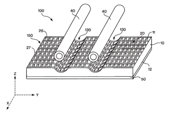
Universal Microreplicated Dielectric Insulation for Electrical Cables
US Patent 11948706
Published April 2, 2024
Inventor: Douglas B. Gundel, Cedar Park, TX, USA
Assignee: 3M Innovative Properties Company, St. Paul, MN, USA
A ribbon cable is described, including a first insulative layer extending along
a length and a width of the cable, and a plurality of spaced apart
substantially parallel conductors extending along the length of the cable.
The insulative layer has opposing top and bottom major surfaces and
defines a plurality of spaced apart cavities extending between the top and
bottom major surfaces of the first insulative layer. The top major surface of
the first insulative layer is deformed in a plurality of spaced apart
substantially parallel regions extending along the length, and arranged
along the width, of the cable. Each deformed region has a shape of a groove
and includes a deformed portion of at least one cavity in the plurality of
cavities. Each conductor is disposed within a corresponding deformed
region of the insulative layer.
Hybrid Cable for Distributed Power Connectivity
US Patent 11942235
Published March 26, 2024
Inventor: Randall Stevens, Lincolnton, NC, USA
Assignee: CommScope Technologies LLC, Hickory, NC, USA
A hybrid cable includes a central strength member, residing in a center of
the cable. At least two insulated conductors are abutting the central
strength member. One or more buffer tubes are included in the cable, each
with at least one optical fiber. One or more filler rods are optionally
included in the cable. A shielding layer and jacket surround the elements. In
one embodiment, four large insulated conductors and two filler rods abut
the central strength member. A first water-blocking tape surrounds the four
large insulated conductors, filler rods and central strength member to form
an inner core. A concentric core surrounds the central core. The concentric
core includes two insulated conductors, plural buffer tubes and a second
water-blocking tape surrounding the two insulated conductors and the
plural buffer tubes. The shielding layer surrounds the concentric core, and
the jacket surrounds the shielding layer. A toning signal carrying medium
may also exist outside of the shielding layer.
Fire Resistant Corrugated Coaxial Cable
US Patent 11942233
Published March 26, 2024
Inventor: William E. Rogers, Danville, CA, USA
Assignee: American Fire Wire, Inc., Minden, NV, USA
A fire resistant corrugated coaxial cable is described that employs a hightemperature, insulating alkaline earth silicate (AES) wool dielectric. The AES
wool dielectric is devoid of water as a constituent. The AES wool may be
survivable under conditions of high heat, such as temperatures specified by
common fire test standards (e.g., 1850°F/1010°C for two hours). The cable is
configured to maintain a relatively coaxial relation between a center
conductor and an outer conductor even under aforementioned fire tests. A
layer of ceramifiable silicone rubber or refractory fiber wrap can surround
the outer conductor and continues to insulate it from the outside if a lowsmoke zero-halogen (LSZH) jacket burns away.
Electric Cable
US Patent 11942241
Published March 26, 2024
Inventor and Assignee: Lubomir Dostal, Winchester, MA, USA
An improved electric cable is disclosed herein. The resistance of the electric
cable of the present disclosure is surprisingly decreased despite a reduction
in the cross-sectional area of the conductor when at least one metal slug is
positioned at an end of the cable. Conductor wires, which may or may not
be individually insulated, may extend around a metal slug or through an
aperture of the slug. In combination with at least one metal slug, the cross-sectional area of individual wires or the amount of wires within a stranded
wire cable may be substantially reduced without seeing an expected
proportionate increase in electrical resistance, and surprisingly, a decrease
in resistance may be observed.
Cable Processing Machine System and Method for Removing One or More
Cables from a Removal Trough of a Cable Processing Machine System
US Patent 11936154
Published March 19, 2024
Inventors: Alois Conte, Ebikon, Switzerland; Nils Furrer, Thalwil, Switzerland;
and Dominik Feubli, Kriens, Switzerland
Assignee: Komax Holding AG, Dierikon, Switzerland
A cable processing machine system includes a cable processing machine for
processing a cable, a cable tray for receiving cables processed by the cable
processing machine and a removal trough, the cable tray being pivotable to
transfer cables from the cable tray into the removal trough when the cable
tray pivots. The removal trough includes an exit conveyor belt for conveying
the cables along a transport direction away from the cable processing
machine to an end of the removal trough.
Power Cable Assembly for a Power Distribution System Having an Integrated Cooling System
US Patent 11935672
Published March 19, 2024
Inventors: Dominik Kawalec, Brzoskwinia, Poland; Monika Pieszka-Lyson,
Cracow, Poland; Pawel Kozak, Cracow, Poland; Grzegorz Porebski, Podłęże,
Poland; and Grzegorz Paletko, Zabierzów, Poland
Assignee: Aptiv Technologies AG, Schaff hausen, Switzerland A high voltage
power cable assembly for a power distribuantion system of a vehicle
incorporating an integrated cooling system is presented. The power cable
assembly comprises first and second electrical conductors spaced apart
from one another and extending longitudinally. The power cable assembly
further comprises a longitudinally extending cooling tube arranged between
the first and second electrical conductors such that opposing portions of an
external surface of the cooling tube are provided in direct contact with
corresponding portions of the insulating material of the electrical
conductors over a heat exchange region so as to transfer heat from the
electrically conductive core of the electrical conductors to a coolant medium
circulating in an internal channel of the cooling tube.
Filtering Cable
US Patent 11929189
Published March 12, 2024
Inventors: Yunan Han, Beijing, China; and Xueying Han, Beijing, China
Assignee: Yunan Han, Beijing, China
The present application discloses a filtering cable, which solves the problem
that the cable in the related art cannot ensure a simple and reasonable
structural design while having good filter performance. One or several core
wires and N defective conductor layers surrounding the core wires are
sequentially provided from inside to outside in the cross section in the
radial direction of the filtering cable; wherein the defective conductor layer
has an etching pattern; the etching pattern is distributed in the axial
direction of the filtering cable; the etching pattern is used to make the
filtering cable equivalent to a preset filter circuit to filter the signal
transmitted in the filtering cable.
Sheathed Fiberglass Heater Wire
US Patent 11920853
Published March 5, 2024
Inventors: Maurizio Francesco Pasqual, San Luis Potosí, Mexico; Jose Jesus
Reyes Soto, San Luis Potosí, Mexico; Alessandro Trevisol, San Luis Potosí,
Mexico; and Pierpaolo Campeol, San Luis Potosí, Mexico
Assignee: Zoppas Industries de Mexico S.A., de C.V., San Luis Potosí, Mexico
An apparatus is disclosed. The apparatus includes a resistive wire having a
circumference. The apparatus further includes a first fiberglass layer
disposed about the circumference of the resistive wire and along a length of
the resistive wire. The apparatus further includes a second fiberglass layer.
The apparatus further includes a third fiberglass layer, the second fiberglass
layer disposed between the first fiberglass layer and the third fiberglass
layer, the third fiberglass layer forming an outer layer and surrounding the
second fiberglass layer.
Pre-Terminated Optical Cable
US Patent 11914209
Published February 27, 2024
Inventors: John Shuman, Yorba Linda, CA, USA: and Ian James Griffiths,
Milan, Italy
Assignee: Prysmian S.p.A., Milan, Italy
An optical cable includes a main body and a termination segment extending
from an end of the main body. The main body includes middle portions of
optical fibers. The termination segment includes end portions of the optical
fibers and multi-fiber connectors attached to the end portions of the optical
fibers. The multi-fiber connectors are staggered along the length of the
termination segment.