

Patents for July 2026
Wire & Cable Industry patents compiled by the editors of WCTI for July 2026 from the United States Patent and Trademark Office (USPTO)
Apparatus and Method for Packaging Wire or Cable in a Barrel or Drum Container
US Patent 12654980
Published June 16, 2026
Inventors: William T. Bigbee, Jr., Hawkins, TX, USA; John L. Rhoads, Lewisville, TX, USA; Andrew P. Hull, McKinney, TX, USA; and Benjamin L. Weatherford, Princeton, TX, USA
Assignee: Encore Wire Corporation, McKinney, TX, USA
An apparatus for the accumulation of wire or cable, the apparatus including a collapsible reel assembly, the collapsible reel assembly including a central hollow arbor, a fixed inner support structure axially centered on and rigidly attached to the central hollow arbor, wherein the fixed inner support has a first end and a second end, a fixed flange, axially centered on and attached to the first end of the fixed inner support structure, a removable flange, axially centered on and removably attached to the second end of the fixed inner support structure opposite the fixed flange and an inner drum assembly. The inner drum assembly including a plurality of moving inner support structures movably attached to the fixed inner support structure and a plurality of inwardly-collapsible drum segments. Wherein the inwardly-collapsible drum segments collapse inward after the removable flange is removed from the collapsible reel assembly.
Wire Spool Clutch
US Patent 12654249
Published June 16, 2026
Inventors: Adam E. Link, Grafton, OH, USA; and Matthew A. Weeks, Walloon, Australia
Assignee: Lincoln Global, Inc., Santa Fe Springs, CA, USA
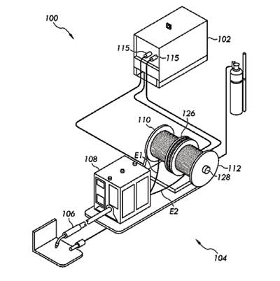
A welding or additive manufacturing wire drive system includes a spindle. First and second welding wire spools are mounted on the spindle. The spools include a flange, a mounting hub, a barrel, and a wire electrode wound on the barrel. At least two drive rolls simultaneously draw first and second wire electrodes from the spools. A clutch disk is mounted on the spindle and has respective frictional surfaces in contact with one or both of the flange and mounting hub on the spools to frictionally engage the spools. The clutch disk allows the spools to slip relative to each other during an operation of the at least two drive rolls such that the spools rotate at different speeds while the wire electrodes are drawn from the spools.
Partitioned Superconducting Cable
US Patent 12658342
Published June 16, 2026
Inventors: Alexey Radovinsky, Cambridge, MA, USA; Charlie Sanabria, Shirley, MA, USA; Christopher Craighill, Cambridge, MA, USA; Krishna Kiran Kumar Uppalapati, North Billerica, MA, USA; Alexander Creely, Boston, MA, USA; and Daniel Brunner, Cambridge, MA, USA
Assignee: Massachusetts Institute of Technology (MIT), Cambridge, MA, USA; and Commonwealth Fusion Systems LLC, Devens, MA, USA
Described is a cable comprising a plurality of high temperature superconductor (HTS) components, a plurality of electrically conductive segments extending along a length of the cable, each of the plurality of electrically conductive segments comprising one of the plurality of HTS components, and an electrically insulating material arranged between adjacent ones of the plurality of electrically conductive segments.
Data Cable and Electronic Device
US Patent 12646892
Published June 2, 2026
Inventor: Dongping Nie, Dongguan, China
Assignee: Vivo Mobile Communication Co., Ltd., Dongguan, China
This application provides a data cable and an electronic device. The data cable includes an AM connector, a Type-C connector, a connection cable and at least one capacitor. Two ends of the connection cable are respectively electrically connected to the AM connector and the Type-C connector. The connection cable includes: an aluminum foil configured to shield an electromagnetic wave, where accommodation space is formed on an inner side of the aluminum foil; two power lines, two signal lines and two internal grounding wires disposed in the accommodation space on the inner side of the aluminum foil; and an external grounding wire disposed on an outer side of the aluminum foil. The power lines are configured to provide a power supply, and the signal lines are configured to transmit a USB signal.
Compact Cable Assembly
US Patent 12645026
Published June 2, 2026
Inventors: Adam Verne Broughton, Harrisburg, PA, USA; David Donald Erdman, Hummelstown, PA, USA; Josiah D. Kadar-Kallen, Harrisburg, PA, USA; and Michael Aaron Kadar-Kallen, Harrisburg, PA, USA
Assignee: CommScope Technologies LLC, Claremont, NC, USA
Optical fibers of a multi-fiber cable are grouped into connection units. The distal ends of the fibers of each connection unit are terminated at a connection unit body that attaches to a tapering cable core formed of longer ones of the connection units. After deployment of the cable, two or more connection units can be stacked together to form a connector or inserted into a connector shell. Prior to deployment of the cable, at least some of the connection units are spaced from each other along the cable. For example, individual connection units may be disposed at one end of the tapering cable core and stacks of connection units may be disposed at the other end of the tapering cable core.
Armored Cable Coil Tie-In Detector
US Patent 12646899
Published June 2, 2026
Inventors: Casey A. Gomez, McKinney, TX, USA; and Jeremy T. Smith, The Colony, TX, USA
Assignee: Encore Wire Corporation, McKinney, TX, USA
A system and method of detecting a tie-in on a cable is disclosed. The method includes the steps of pulling a cable from a payoff reel; scanning the cable for a visual cue; detecting the visual cue; stopping the pull of the cable; cutting the cable; and discarding the cable portion with the visual cue.
Communication Cable, Wire Harness and Method for Manufacturing Communication Cable
US Patent 12637552
Published May 26, 2026
Inventors: Tatsuya Shimada, Mie, Japan; Yuta Yasuyoshi, Mie, Japan; and Katsushi Sakamoto, Mie, Japan
Assignees: Autonetworks Technologies, Ltd., Mie, Japan; Sumitomo Wiring Systems, Ltd., Mie, Japan; and Sumitomo Electric Industries, Ltd., Osaka, Japan
Provided are a communication cable that includes a resin composition formed by adding a halogenated flame retardant and a flame retardant auxiliary to an olefin-based polymer and is excellent in stability of the communication properties and heat resistance, a wire harness that includes such a communication cable and a manufacturing method according to which such a communication cable can be manufactured with high productivity. A communication cable 1 includes a signal wire 10 constituted by a pair of insulated wires 11 each having a conductor 12 and an insulating coating 13 covering the outer circumference of the conductor 12 and an insulating external layer 20 covering the outer circumference of the signal wire 10. The characteristic impedance is within a range of 100±10Ω.
Highly Flame-Retardant UTP Cable
US Patent 12640285
Published May 26, 2026
Inventors: In Ha Kim, Seocho-gu, South Korea; and Yu Min Kim, Gwangmyeong-si, South Korea
Assignee: LS Cable & System Ltd., Anyang-si, South Korea
A highly flame-retardant UTP cable may have a plurality of pair units formed by a plurality of conductive wires twisted together, wherein each conductive wire includes a conductor, an insulator surrounding the conductor, an outer jacket surrounding the plurality of pair units, and a separator including one or more partition walls disposed between the plurality of pair units, wherein any cross-section of the cable has a cross-sectional limited oxygen index, of 57% or more.
Marine Cable for Offshore Wind Power Having an Improved Water-Tree Property
US Patent 12640284
Published May 26, 2026
Inventors: Hyun Jung Jung, Gunpo-si, South Korea; Gi Joon Nam, Seocho-gu, South Korea; Kyoung Soo Kim, Bucheon-si, South Korea; and Yi Seul Yang, Gunpo-si, South Korea
Assignee: LS Cable & System Ltd., Anyang-si, South Korea
A marine cable may be provided with at least one core including a conductor and an insulating layer that surrounds the conductor, such that sizes of water trees, caused by diffusion of moisture, in the insulating layer are controlled.
Optical Fiber Cable and Method for Manufacturing Optical Fiber Cable
US Patent 12631842
Published May 19, 2026
Inventors: Fumiaki Sato, Osaka, Japan; Kenta Tsuchiya, Osaka, Japan; and Eimi Kasai, Osaka, Japan
Assignee: Sumitomo Electric Industries, Ltd., Osaka, Japan
An optical fiber cable includes: a spacer including a plurality of ribs and a plurality of grooves defined by the plurality of ribs; a plurality of optical fiber units accommodated in each of the plurality of grooves; and a cable sheath configured to cover the spacer and the plurality of optical fiber units. The spacer and the cable sheath are integrally formed.
3D Printing Wire and Preparation Method Therefor, 3D Printing Method and Printing Apparatus
US Patent 12,629,889
Published May 19, 2026
Inventors: Mingyang Hao, Suzhou, China; and Xiaofan Luo, Suzhou, China
Assignee: JF Polymers (Suzhou) Co., Ltd., Suzhou, China
A 3D printing wire, a method for preparing the 3D printing wire, a 3D printing method and a 3D printing apparatus are provided. The method for preparing the 3D printing wire includes co-extruding a first polymer matrix composite and a second polymer matrix composite to produce a 3D printing wire with a core-shell structure. In the 3D printing wire with the core-shell structure, a shell structure formed by the second polymer matrix composite is wrapped around a core structure formed by the first polymer matrix composite. A filler material volume fraction of the first polymer matrix composite is larger than a filler material volume fraction of the second polymer matrix composite. The material for the shell structure includes an unfilled polymer material with a composite filling content of zero.
Insulated Electric Wires
US Patent 12,633,431
Published May 19, 2026
Inventors: Eun Ah Kim, Suwon-si, South Korea; Dong Jin Seo, Gunpo-si, South Korea; and Jae Yong Kim, Seoul, South Korea
Assignee: LS Eco-Materials, Ltd., Gumi-si, South Korea
The present disclosure relates to an insulated electric wire, and more particularly, to an insulated electric wire that has characteristics of a low dielectric constant and a high partial discharge inception voltage (PDIV) by forming a plurality of micropores inside insulating material of an insulating layer. According to the present disclosure, the insulated electric wire may have the plurality of micropores evenly dispersed inside the insulating material of the insulating layer to have the low dielectric constant without lowering the thermal and mechanical properties and increase the PDIV, so the insulated electric wire can be used as the insulated electric wire for the next-generation electric vehicle motors that use a higher voltage than the existing voltage.
Electrically Insulated Cable
US Patent 12,626,839
Published May 12, 2026
Inventors: Yutaka Matsumura, Osaka, Japan; Shigeyuki Tanaka, Osaka, Japan; Taro Fujita, Osaka, Japan; Takumi Ooshima, Kanuma, Japan; and Jo Yagisawa, Kanuma, Japan
Assignee: Sumitomo Electric Industries, Ltd., Osaka, Japan
An electrically insulated cable comprising: a core electric wire; a tape member covering the core electric wire; and a covering layer covering the tape member, wherein: the core electric wire includes a plurality of insulated electric wires; the insulated electric wires each include a conductor and an insulating layer covering the conductor; the tape member is a film; and the tape member has a breaking elongation of 50% or less.
Wire Processing Device
US Patent 12,627,108
Published May 12, 2026
Inventor: David Alan College, Middletown, PA, USA
Assignee: TE Connectivity Solutions GmbH, Switzerland
A wire holding device comprises a base and a clamping assembly. The clamping assembly includes a first gripper attached to the base and adapted to grip a first wire of a cable and a second gripper adapted to grip a second wire of the cable. The second gripper is movable relative to, and operable independently of, the first gripper.
Self-Regulating Heater Cable with Buffer Layer
US Patent 12,621,908
Published May 5, 2026
Inventors: Jennifer Robison, San Carlos, CA, USA; Wade DePolo, Sunnyvale, CA, USA; Sirarpi B. Jenkins, Menlo Park, CA, USA; Linda D.B. Kiss, San Mateo, CA, USA; Marcus Kleinehanding, Tolochenaz, Switzerland; and Paul Becker, San Carlos, CA, USA
Assignee: Chemelex Europe GmbH, Schaffhausen, Switzerland
Embodiments of the invention provide self-regulating heater cables utilizing substantially solid polymeric buffer layers surrounding the heating elements having improved heat transfer efficiency as well as improved reliability and endurance. The assembly includes first and second power supply wires configured to carry electrical power and separated by a solid spacer, a substantially solid electrically-insulating buffer layer in thermal contact with the heating element and a cable jacket including a polymeric outer surface and an inner metallic sheath surrounding the buffer layer and in thermal contact with the buffer layer. The buffer layer includes a polymeric material having a thermal conductivity greater than air at standard temperature and pressure and surrounds the heating element, power supply wires and spacer.
Optoelectronic Cable
US Patent 12,619,041
Published May 5, 2026
Inventors: Kai-Hsuan Lin, New Taipei City, Taiwan; and Yi-Chieh Cheng, New Taipei City, Taiwan
Assignee: Elka International Ltd., New Taipei City, Taiwan
An optoelectronic cable comprises an optical fiber wire disposed at the center of the optoelectronic cable, with an armoring layer that is arranged at a periphery of the optical fiber wire. A plurality of electric wires is disposed around the periphery of the optical fiber wire, and an outer sheath is disposed as an outermost layer of the optoelectronic cable. By arranging the armoring layer at the periphery of the innermost optical fiber wire, optical fibers therein can be protected from being damaged by external forces. The overall assembly can also effectively reduce the total diameter, resulting in a softer and more flexible optoelectronic cable highly convenient for packaging and installation.
In-Vehicle Communication System and Communication Cable
US Patent 12,620,507
Published May 5, 2026
Inventors: Kenta Kobayashi, Mie, Japan; Kenichiro Iwama, Mie, Japan; and Ayumu Minagawa, Mie, Japan
An in-vehicle communication system includes a transmitter that transmits a differential signal, a receiver that receives the differential signal, and a communication cable that connects between the transmitter and the receiver and transmits the differential signal. The communication cable includes a twisted wire, a sheath covering the twisted wire, and a talc layer provided between the twisted wire and the sheath. The sheath includes a pair of ribs located across a straight line connecting a conductor center of a first coated wire and a conductor center of a second coated wire in a transverse section of the communication cable. The talc layer is provided along the surface of the twisted wire.
Steel Wire
US Patent 12,612,675
Published July 28, 2026
Inventors: Shinya Teramoto, Tokyo, Japan; Yutaka Neishi, Tokyo, Japan; Michimasa Aono, Tokyo, Japan; Satoru Mineta, Tokyo, Japan; Shoichi Suzuki, Tokyo, Japan; and Tatsuro Ochi, Tokyo, Japan
Assignees: Nippon Steel Corporation, Tokyo, Japan; and Nippon Steel SG Wire Co., Ltd., Tokyo, Japan
A steel wire which has excellent cold coiling workability, and which has an excellent fatigue limit when made into a spring is provided. A chemical composition of the steel wire according to the present, embodiment containing, in mass %, C: 0.50 to 0.80%, Si: 1.20 to less than 2.50%, Mn: 0.25 to 1.00%, P: 0.020% or less, S: 0.020% or less, Cr: 0.40 to 1.90%, V: 0.05 to 0.60%, and N: 0.0100% or less, with the balance being Fe and impurities. In the steel wire, a number density of V-based precipitates having a maximum diameter ranging from 2 to 10 nm is 5000 to 80000 pieces/μm3.
Flux-Cored Wire
US Patent 12,611,738
Published July 28, 2026
Inventors: Hirofumi Maniwa, Fujisawa, Japan; Yoshihiko Kitagawa, Fujisawa, Japan; and Masamichi Suzuki, Fujisawa, Japan
Assignee: Kobe Steel, Ltd., Kobe, Japan
A flux cored wire which exhibits excellent welding workability during gas-shielded arc welding while enabling the achievement of a welded metal that has excellent tensile strength and toughness at low temperatures. The wire is obtained by filling a sheath with a flux and is adequately controlled with respect to the corresponding chemical components, while having a θ of from 10.0 to 30.0 as calculated by the mathematical formula (I): θ=4.1×α−3.2×γ−32.3. The respective contents, in mass %, of Si, Cr, Mo, Ti, C, N, Mn, Cu and Ni, relative to the total mass of the wire, are respectively represented by [Si], [Cr], [Mo], [Ti], [C], [N], [Mn], [Cu] and [Ni], α=0.02×[Si]+[Cr]+1.20×[Mo]+0.3×[Ti]+0.30 and γ=24×[C]+28×[N]+0.25×[Mn]+0.5/[Cu]+1.10×[Ni].
Internal Cooling of Power Cables and Power Umbilicals
US Patent 12,614,649
Published July 28, 2026
Inventor: Oyvind Iversen, Ski, Norway
Assignee: Nexans, Courbevoie, France
A power cable has an outer sheath, at least one conductor element arranged within the outer sheath and a filler element arranged within the outer sheath. The filler element is hollow such that a cooling fluid can be passed through the filler element. A temperature sensor is configured to measure the internal temperature of the cable.
Composite Cable
US Patent 12,614,650
Published July 28, 2026
Inventors: Masashi Moriyama, Tokyo, Japan; Detian Huang, Tokyo, Japan; Masanori Kobayashi, Tokyo, Japan; Atsuro Yaguchi, Tokyo, Japan; and Kimika Kudo, Tokyo, Japan
Assignee: Proterial, Ltd., Tokyo, Japan
A composite cable having an outer diameter of 1.0 mm or less is provided with a cable core including multiple signal lines, a power line with an outer diameter smaller than an outer diameter of the signal line, and a drain wire with an outer diameter smaller than the outer diameter of the power line, and a sheath covering around the cable core. An outermost layer of the signal line is a shield layer, and either one of the power line or the drain wire is arranged in each valley-like space between the multiple signal lines arranged in contact with one another inside the cable core.
Alloy Wire Rod and Preparation Method and Application Thereof
US Patent 12,606,889
Published July 21, 2026
Inventors: Minfeng Tang, Xiamen, China; Yijin Fang, Xiamen, China; Sheng Lv, Xiamen, China; Donghong Guo, Xiamen, China; Xianyue Wu, Xiamen, China; Fusheng Peng, Xiamen, China
Assignee: Xiamen Honglu Tungsten Molybdenum Industry Co., Ltd., Xiamen, China
The present disclosure relates an alloy wire rod and a preparation method and application thereof. The alloy wire rod is made of a tungsten alloy and the tungsten alloy contains tungsten and an oxide of lanthanum. The alloy wire rod has a wire diameter of equal to or less than 100 μm; and the alloy wire rod has a tensile strength of greater than 3800 MPa. The wire diameter of the alloy wire rod is equal to or less than 60 μm; the diameter of a push-pull core wire of the alloy wire rod is less than 350 μm; the elastic ultimate strength of the alloy wire rod is greater than 2500 MPa; and the tensile strength of the alloy wire is greater than 4200 MPa. In the present disclosure, the alloy wire rod having ultra-high strength and good toughness is obtained by doping an oxide of lanthanum.
Tungsten Wire, Tungsten Wire Processing Method Using the Same and Electrolyzed Wire
US Patent 12,606,890
Published July 21, 2026
Inventors: Hitoshi Aoyama, Yokohama, Japan; Hideaki Baba, Yokohama, Japan; and Kenji Tomokiyo, Yokohama, Japan
Assignee: Niterra Materials Co., Ltd., Yokohama, Japan
A tungsten wire according to an embodiment is a tungsten wire made of a W alloy containing rhenium, and includes a mixture on at least a part of a surface thereof, the mixture contains W, C and O as constituent elements and taking a radial cross-sectional thickness of the mixture as A mm and a diameter of the tungsten wire as B mm, an average value of a ratio A/B of A to B is 0.3% to 0.8%.
Superconducting Cables for Electrical Submersible Pump Motors
US Patent 12,609,217
Published July 21, 2026
Inventors: Hassan Mansir, Frimley, UK; and Robert Charles De Long, Tulsa, OK, USA
Assignee: Halliburton Energy Services, Inc., Houston, TX, USA
A cable structure for use in a wellbore formed in a subsurface formation. The cable structure comprises superconducting material configured to provide power to a downhole tool in the wellbore. The cable structure comprises a cryogenic liquid supply channel configured to supply fluid to reduce temperature of the superconducting material. The cable structure comprises one or more cryogenic liquid return channels.
Optical Fiber Cable With Tensile Material Between the Inner Reinforcing Projection
US Patent 12,601,884
Published July 14, 2026
Inventors: Young Bin Song, Seoul, South Korea; and June Hyong Kim, Suwon-si, South Korea
Assignee: HYESUNG Cable & Communication Inc., Iksan-si, South Korea
The present disclosure relates to an optical fiber cable with tensile material between the inner reinforcing projection, and more specifically, to minimize the increase in diameter even when various interior materials for strength reinforcement are built in, thereby ensuring durability. This relates to an optical cable equipped with a tension member between reinforcing protrusions inside the covering which can be expected to have advantage effects such as reduced manufacturing costs and improving installation workability with a miniaturized structure.
Hybrid Superconducting Cable
US Patent 12,603,196
Published July 14, 2026
Inventor: Glenn Auld Knierim, Littleton, CO, USA
Assignee: Electric Mayhem, LLC, Littleton, CO, USA
A hybrid cable generally comprising a superconducting material and a material consisting at least partially of a conventional conductor. In operation, the hybrid cable is chilled to superconducting temperatures, wherein current primarily passes through the superconducting material. If the superconducting material loses performance, e.g., is quenched, current will flow primarily through the chilled conventional conductor. In the event hybrid cable temperature further increases, the current will travel through the conventional conductor at its normal capacity.
Flame-Retardant Cable With Self-Extinguishing Coating Layer
US Patent 12,595,391
Published July 7, 2026
Inventors: Pauline Audebet, Milan, Italy; Vito Scrima, Milan, Italy; Luigi Caimi, Lomagna, Italy; Flavio Casiraghi, Osnago, Italy; Serge Colombier, Malay le Grand, France; Sergio Gutierrez, Vilanova i la Geltrú, Spain
Assignee: Prysmian S.p.A., Milan, Italy
A flame-retardant cable is disclosed, the cable having a core comprising at least one conductor, and a coating layer made from a low smoke zero halogen flame-retardant polymer composition comprising an ethylene vinyl acetate copolymer and a polyethylene having a density lower than 0.925 g/cm3 as polymeric base added with: a) from 110 to 160 phr of at least one metal hydroxide; b) from 1 to 7 phr of a phyllosilicate clay; c) from 1 to 7 phr of melamine or a derivate thereof; and d) from 1 to 7 phr of zinc borate.
Steel Wire for Machine Structural Parts and Method for Manufacturing the Same
US Patent 12,595,527
Published July 7, 2026
Inventors: Yosuke Matsumoto, Kobe, Japan; Kenshi Ikeda, Kobe, Japan; Takuya Kochi, Kobe, Japan; Masayuki Sakata, Kobe, Japan; Tatsunori Uchida, Kobe, Japan; Koji Yamashita, Kobe, Japan; Yuta Inoue, Kobe, Japan
Assignee: Kobe Steel, Ltd., Kobe, Japan
A steel wire for machine structural parts may include Fe, inevitable impurities and, by mass: 0.05 to 0.60% C; 0.005 to 0.50% Si; 0.30 to 1.20% Mn; more than 0 to 0.050% P; more than 0 to 0.050% S; 0.001 to 0.10% Al; more than 0 to 1.5% Cr; and more than 0 to 0.02% N. An area of cementite present at ferrite grain boundaries in an area of all cementite of the steel wire may be 32% or more. When a C content (% by mass) of a steel is expressed as [C], an average circular-equivalent diameter of all the cementite is (1.668-2.13 [C]) μm or more and (1.863-2.13 [C]) μm or less.